


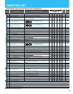
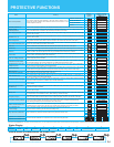

= Allowed
= Not permitted
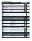
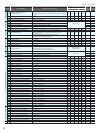
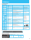
Code Function Name Monitored data or setting
Default Setting
Setting
during
operation
(allowed or not)
Change
during
operation
(allowed or not)
SJ700/SJ700D(CTmode)
SJ700B
-FE -FU -F -F -FU
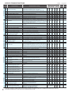
Communication
function
C076
Selection of the operation after
communication error
00 (tripping), 01 (tripping after decelerating and stopping the motor), 02 (ignoring
errors), 03 (stopping the motor after free-running), 04 (decelerating and stopping
the motor)
02 02 02 02 02
C077
Communication timeout limit before tripping
0.00 to 99.99 (s)
0.00 0.00 0.00 0.00 0.00
C078
Communication wait time
0. to 1000. (ms)
0. 0. 0. 0. 0.
C079
Communication mode selection
00 (ASCII), 01 (Modbus-RTU)
00 00 00 00 00
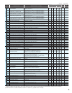
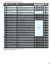
Adjustment
C081
O input span calibration
0. to 9999., 1000 to 6553 (10000 to 65530)
Factory set
C082
OI input span calibration
0. to 9999., 1000 to 6553 (10000 65530)
C083
O2 input span calibration
0. to 9999., 1000 to 6553 (10000 65530)
C085
Thermistor input tuning
0.0 to 999.9, 1000.
C091
Debug mode enable
(Do not change this parameter, which is intended for factory adjustment.)
00 00 00 00 00
Others
C101
UP/DOWN memory mode selection
00 (not storing the frequency data), 01 (storing the frequency data)
00 00 00 00 00
C102
Reset mode selection
00 (resetting the trip when RS is on), 01 (resetting the trip when RS is off ),
02 (enabling resetting only upon tripping [resetting when RS is on]),
03 (resetting only trip)
00 00 00 00 00
C103
Restart mode after reset
00 (starting with 0 Hz), 01 (starting with matching frequency),
02 (restarting with active matching frequency)
00 00 00 00 00
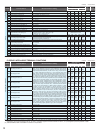
Meter adjustment
C105
FM gain adjustment
50. to 200. (%)
100. 100. 100. 100. 100.
C106
AM gain adjustment
50. to 200. (%)
100. 100. 100. 100. 100.
C107
AMI gain adjustment
50. to 200. (%)
100. 100. 100. 100. 100.
C109
AM bias adjustment
0. to 100. (%)
0. 0. 0. 0. 0.
C110
AMI bias adjustment
0. to 100. (%)
20. 20. 20. 20. 20.
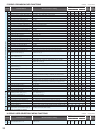
Terminal
C111
Overload setting (2)
SJ700/SJ700D (CT):0.0 to 2.00 x "rated current" (A)
<75kW and over:0.0 to 1.80 x "rated current">
SJ700D (VT)/SJ700B:0.0 to 1.50 x "rated current" (A)
Rated current of
inverter x 1.00
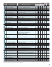
Adjustment
C121
O input zero calibration
0. to 9999., 1000 to 6553 (10000 to 65530)
Factory setC122
OI input zero calibration
0. to 9999., 1000 to 6553 (10000 to 65530)
C123
O2 input zero calibration
0. to 9999., 1000 to 6553 (10000 to 65530)
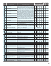
Output terminal operation function
C130
Output 11 on-delay time
0.0 to 100.0 (s)
0.0 0.0 0.0 0.0 0.0
C131
Output 11 off -delay time
0.0 to 100.0 (s)
0.0 0.0 0.0 0.0 0.0
C132
Output 12 on-delay time
0.0 to 100.0 (s)
0.0 0.0 0.0 0.0 0.0
C133
Output 12 off -delay time
0.0 to 100.0 (s)
0.0 0.0 0.0 0.0 0.0
C134
Output 13 on-delay time
0.0 to 100.0 (s)
0.0 0.0 0.0 0.0 0.0
C135
Output 13 off -delay time
0.0 to 100.0 (s)
0.0 0.0 0.0 0.0 0.0
C136
Output 14 on-delay time
0.0 to 100.0 (s)
0.0 0.0 0.0 0.0 0.0
C137
Output 14 off -delay time
0.0 to 100.0 (s)
0.0 0.0 0.0 0.0 0.0
C138
Output 15 on-delay time
0.0 to 100.0 (s)
0.0 0.0 0.0 0.0 0.0
C139
Output 15 off -delay time
0.0 to 100.0 (s)
0.0 0.0 0.0 0.0 0.0
C140
Output RY on-delay time
0.0 to 100.0 (s)
0.0 0.0 0.0 0.0 0.0
C141
Output RY off -delay time
0.0 to 100.0 (s)
0.0 0.0 0.0 0.0 0.0
C142
Logical output signal 1 selection 1
Same as the settings of C021 to C026 (except those of LOG1 to LOG6)
00 00 00 00 00
C143
Logical output signal 1 selection 2
Same as the settings of C021 to C026 (except those of LOG1 to LOG6)
00 00 00 00 00
C144
Logical output signal 1 operator selection
00 (AND), 01 (OR), 02 (XOR)
00 00 00 00 00
C145
Logical output signal 2 selection 1
Same as the settings of C021 to C026 (except those of LOG1 to LOG6)
00 00 00 00 00
C146
Logical output signal 2 selection 2
Same as the settings of C021 to C026 (except those of LOG1 to LOG6)
00 00 00 00 00
C147
Logical output signal 2 operator selection
00 (AND), 01 (OR), 02 (XOR)
00 00 00 00 00
C148
Logical output signal 3 selection 1
Same as the settings of C021 to C026 (except those of LOG1 to LOG6)
00 00 00 00 00
C149
Logical output signal 3 selection 2
Same as the settings of C021 to C026 (except those of LOG1 to LOG6)
00 00 00 00 00
C150
Logical output signal 3 operator selection
00 (AND), 01 (OR), 02 (XOR)
00 00 00 00 00
C151
Logical output signal 4 selection 1
Same as the settings of C021 to C026 (except those of LOG1 to LOG6)
00 00 00 00 00
C152
Logical output signal 4 selection 2
Same as the settings of C021 to C026 (except those of LOG1 to LOG6)
00 00 00 00 00
C153
Logical output signal 4 operator selection
00 (AND), 01 (OR), 02 (XOR)
00 00 00 00 00
C154
Logical output signal 5 selection 1
Same as the settings of C021 to C026 (except those of LOG1 to LOG6)
00 00 00 00 00
C155
Logical output signal 5 selection 2
Same as the settings of C021 to C026 (except those of LOG1 to LOG6)
00 00 00 00 00
C156
Logical output signal 5 operator selection
00 (AND), 01 (OR), 02 (XOR)
00 00 00 00 00
C157
Logical output signal 6 selection 1
Same as the settings of C021 to C026 (except those of LOG1 to LOG6)
00 00 00 00 00
C158
Logical output signal 6 selection 2
Same as the settings of C021 to C026 (except those of LOG1 to LOG6)
00 00 00 00 00
C159
Logical output signal 6 operator selection
00 (AND), 01 (OR), 02 (XOR)
00 00 00 00 00
Input terminal response
C160
Input terminal response time setting 1
0. to 200. (×2ms)
11111
C161
Input terminal response time setting 2
0. to 200. (×2ms)
11111
C162
Input terminal response time setting 3
0. to 200. (×2ms)
11111
C163
Input terminal response time setting 4
0. to 200. (×2ms)
11111
C164
Input terminal response time setting 5
0. to 200. (×2ms)
11111
C165
Input terminal response time setting 6
0. to 200. (×2ms)
11111
C166
Input terminal response time setting 7
0. to 200. (×2ms)
11111
C167
Input terminal response time setting 8
0. to 200. (×2ms)
11111
C168
Input terminal response time setting FW
0. to 200. (×2ms)
11111
other
C169
Multistage speed/position determination time
0. to 200. (×10ms)
00000
21