


HMR3100
SENSOR PRODUCTS
Solid State Electronics Center • www.magneticsensors.com • (800) 323-8295 • Page 3
converters (ADC) onboard a microcontroller (µC) integrated circuit. The microcontroller integrated circuit periodically
samples the amplified sensor voltages, performs the offset corrections, and computes the heading. This
microcontroller also performs the external serial data interface and other housekeeping functions such as the
calibration routine.
The power supply for the HMR3100 circuit board is to be about a +3 to +5 volt range allowing the user to provide a
single lithium battery to logic level supply voltages. The power supply architecture is a single ground system for single
ended supply sources (+ and ground return).
Note the “North Arrow” printed on the HMR3100 circuit board top side. This is the mechanical reference for product
alignment purposes. When placed on the development kit’s RS-232 motherboard assembly, this arrow also points
toward the 9-volt batterypin block on the motherboard (away from the RJ-11 jack).
Pin Configuration
Pin Number Pin Name Description
1 VCC Power Supply Input
2 NC No Connection
3 RTS Ready To Send Input
4 NC No Connection
5 TXD Transmit Data Output
6 RXD Receive Data Input
7 GND Power and Signal Ground
8 NC No Connection
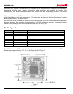
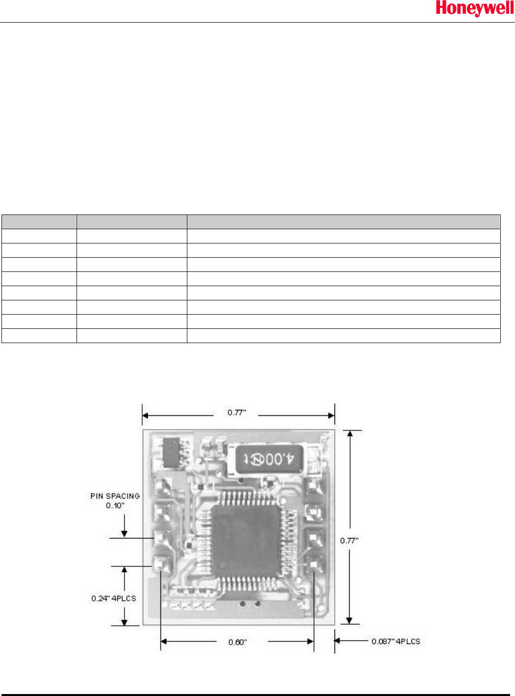
The HMR3100 board is 0.77” on each side with eight pins in groups of four spaced at 0.6” apart in wide-DIP format.
Seated height is approximately 0.275”. Pin 1 is the upper right pin in Figure 1
.
Figure 1
HMR3100 Dimensions