


R7184 INTERRUPTED ELECTRONIC OIL PRIMARY
68-3033
2
SPECIFICATIONS R7184
Models:
Table 1 lists the major features of the R7184 models.
Table 1. R7184 Models.
Model Valve-On Delay (sec) Blower-Off Delay (min) Alarm Contacts Thermostat Terminals T-T
R7184A No No No Yes
R7184B Yes No No jumpered
R7184P Yes Selectable No Yes
R7184U Selectable Selectable Yes Yes
Timing
Valve-on Delay: 0 or 15 seconds.
Blower-off Delay: 0, 2, 4, or 6 minutes, field-selectable using
DIP switch positions 1 and 2.
NOTE: For universal R7184U model, valve-on delay and
blower-off delay timings can be enabled or disabled
(values are zero) in the field using DIP switch
position 3. See installation instructions, form 69-1233.
Electrical Ratings:
Inputs:
Voltage: 102 to 132 Vac, 120 Vac nominal.
Current: 50 mA plus burner motor, valve and ignitor loads.
Frequency: 60 Hz.
Outputs:
Relay Contacts:
Burner: 120 Vac, 10 full load amperes (FLA), 60 locked rotor
amperes (LRA).
NOTE: Reduce burner motor FLA by ignitor load. For
example, the ignitor listed below draws a maximum
of 3A (120 Vac, 360 VA). Reduce the burner motor
FLA to 7A.
Valve: 120 Vac, 1A.
Ignitor: 120 Vac, 360 VA.
Alarm: 30 Vac, 2A.
Thermostat Current Available: 100 mA.
Environmental Ratings:
Operating Ambient Temperature:
-40°F (-40°C) to +150°F (+66°C).
Shipping Temperature: -20°F (-29°C) to +150°F (+66°C).
Humidity: 90% relative humidity at 95°F (35°C) noncondensing.
Approvals:
Underwriters Laboratories Inc. Component Recognized.
Canadian Underwriters Laboratories Inc. Component
Recognized.
OPERATION
The R7184 is a microprocessor-based control. The LED offers
diagnostic information for lockout, recycling and patented cad
cell status. There is a manual reset button to exit the lockout
state and enter the idle state.
TYPICAL CONNECTIONS
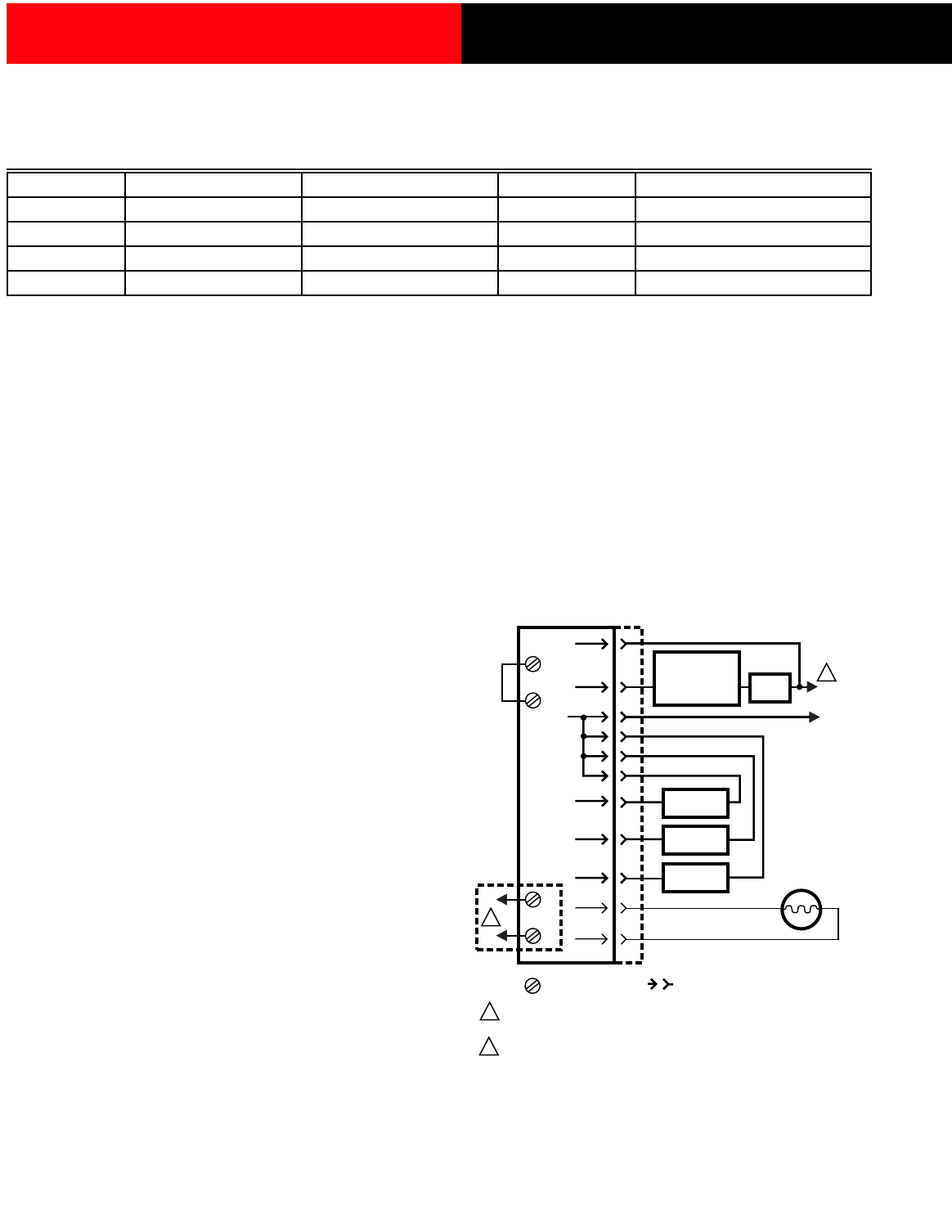
Fig. 1 through 4 show typical R7184 connections.
NOTE: When installing the R7184 with a line voltage
thermostat, connect the line voltage thermostat in
series with the limit controller.
L2
POWER SUPPLY. PROVIDE DISCONNECT MEANS
AND OVERLOAD PROTECTION AS REQUIRED.
OPTIONAL FEATURE ON SELECT MODELS.
1
R7184
LIMIT
IGNITOR
OIL VALVE
M16297
LINE VOLTAGE
THERMOSTAT
OR AQUASTAT
®
CONTROL
L1
(HOT)
1
CAD CELL
2
2
BURNER
MOTOR
L2
LIMIT
JUMPER
VALVE
BURNER
MOTOR
IGNITOR
CAD
CELL
L1
JUNCTION BOX
ALARM
T
T
LEGEND:
SCREW TERMINAL
1/4 IN. QUICK CONNECT TERMINAL
Fig. 1. Typical connection for line voltage thermostat
and R7184B,P,U for valve-on delay/blower-off delay
oil burner system.