


NOTE: If you have a flat-bottomed aluminum boat, some additional adjustment may be needed to
accommodate the rivets on the bottom of the boat (i.e. the gap may need to be a little smaller than 1/8").
This will help you to avoid excessive turbulence at high speeds.
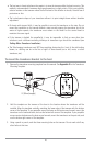
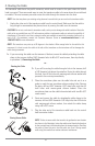
NOTE: If your propeller moves clockwise (in forward, as you're facing the stern of the boat from behind),
mount the transducer on the starboard side, and align the bottom right corner of the mounting bracket with
the bottom of the boat. If your propeller moves counter-clockwise (in forward, as you're facing the stern of
the boat from behind), mount the transducer on the port side, and align the bottom left corner of the
mounting bracket with the bottom of the boat.
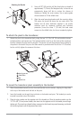
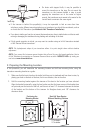
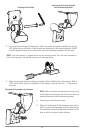
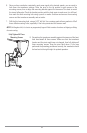
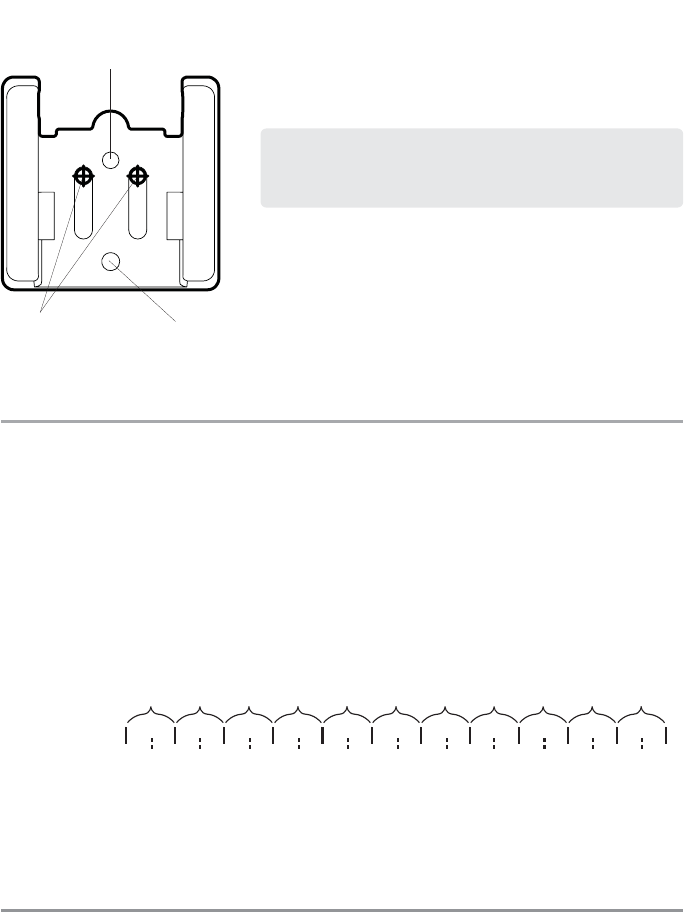
3. Continue to hold the bracket on the transom of the boat, and use
a pencil or marker to mark where to drill the two mounting holes.
Mark the drill holes near the top of each slot, making sure that
your mark is centered in the slot.
4. Make sure that the drill bit is perpendicular to the actual surface
of the transom, NOT parallel to the ground, before you drill. Using
a 5/32” bit, drill the two holes only to a depth of approximately 1”.
NOTE: On fiberglass hulls, it is best to use progressively larger drill bits to
reduce the chance of chipping or flaking the outer coating.
3. Assembling the Transducer and Initial Mounting
In this procedure, you will assemble the transducer using the hardware provided, then mount it and make
adjustments to its position without locking it in place.
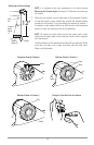
NOTE: You will initially assemble the transducer and the pivot arm by matching the two ratchets to a
numbered position on the transducer knuckle. Further adjustments may be necessary.
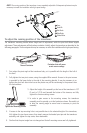
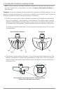
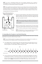
1a. If you already know your transom angle, refer to the chart below for the initial position to use to
set the ratchets. If your transom is angled at 14 degrees (a common transom angle for many
boats) use position 1 for the ratchets. In either case, go to step 2.
or...
1b. If you do not know your transom angle, measure it using a plumb line (weighted nylon string or
monofilament line) exactly 12 inches long. Hold the top of the plumb line against the top of the
transom with your finger, and wait until the line hangs straight down. Using a ruler, measure the
distance from the bottom of the plumb line to the back of the transom, then use the chart.
-2 -1 0 1 2 3 4 5 6 7 8 9 10 11 12 13 14 15 16 17 18 19 20 21 22 23 24
Transom Angle (°)
Bead Alignment
Number
142531425
25 26 27
3
28 29 30
1
Measured Distance (x)
1.1cm
1/2“
0.0 cm
0“
2.5 cm
1“
4.3 cm
1 5/8“
5.9 cm
2 3/8“
7.6 cm
3“
9.3cm
3 5/8“
11.1cm
4 3/8“
12.9cm
5“
14.9cm
5 7/8“
16.9cm
6 5/8“
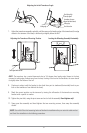
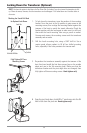
NOTE: The third hole should not be drilled until the angle and
height of the transducer is finalized, which you will not do until a
later procedure.
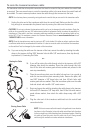
Using the Mounting Bracket to
Mark the Initial Drill Holes
Mark Initial Drill Holes
Fourth Hole
Third Hole
28