


TS Series Conveyors Technical Manual 7610-002-98-29
Issued: 02-15-2006 Revised: N/A
26
SECTION 2: INSTALLATION & OPERATION INSTRUCTIONS
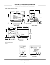
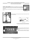
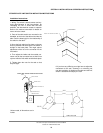
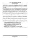
STRIKER PLATE LIMIT SWITCH INSTALLTION INSTRUCTIONS
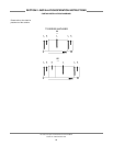
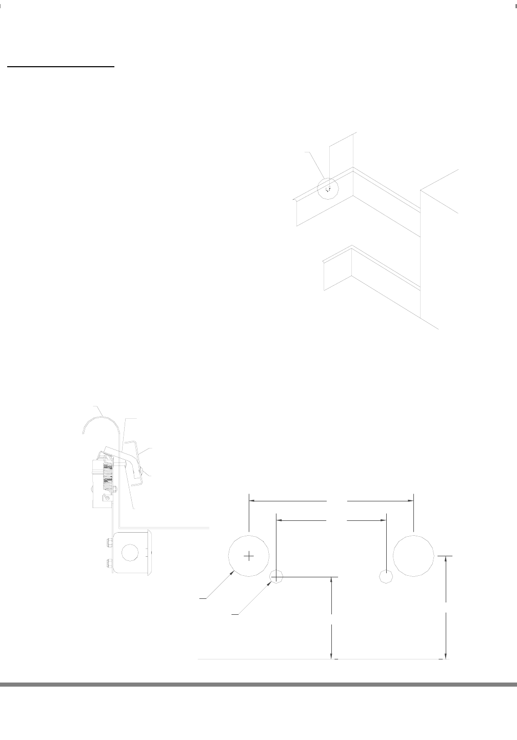
TABLE LIMIT SWITCH THROUGH ROD HOLES
TABLE
SWITCH RODS
STRIKE PLATE
STRIKE PLATE BOLTS
MOUNTING BOLTS
TABLE BOTTOM
3.00
2.00
Ø0.75
Ø0.25
1.50
TABLE BOTTOM
1.875
INSTALL AT FAR END OF TABLE
1/3 RACK WIDTH
Installation Instructions:
1. Wiring: The switch is wired common and nor-
mally open because of the hinge design. By
interupting the line in series with the door
switches, the dishmachine ceases to operate.
Refer to the machine schematic for details on
how to wire the switch.
2. Parts of the table switch are mounted in the
dishtable, at the end of the table and under the
table. See the drawing(s) for the relationship of
the switch to the table.
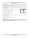
3. Move the limit switch as far down on the two
slots as possible and see that the limit switch is
straight on the base plate. This might require
adjustment of the nut on the connector for the
limit switch.
4. Then adjust the inside and the outside con-
nector nuts for the connector box so that it lines
up even with the limit switch and the base plate.
5. Tighten down the nuts for the seal so that
they are tight.
6. If you have any difficulty you might have to adjust the
connectors to the seal, screwing in or screwing out
until the installation is straight on the table and the limit
switch is actuated correctly by the rack.
Unless noted, all dimensions are in
inches.