


6. HG-MR SERIES/HG-KR SERIES
6 - 12
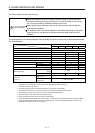
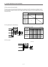
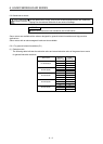
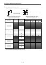
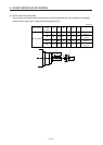
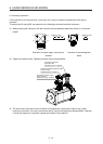
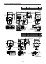
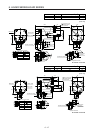
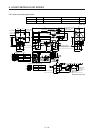
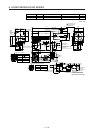
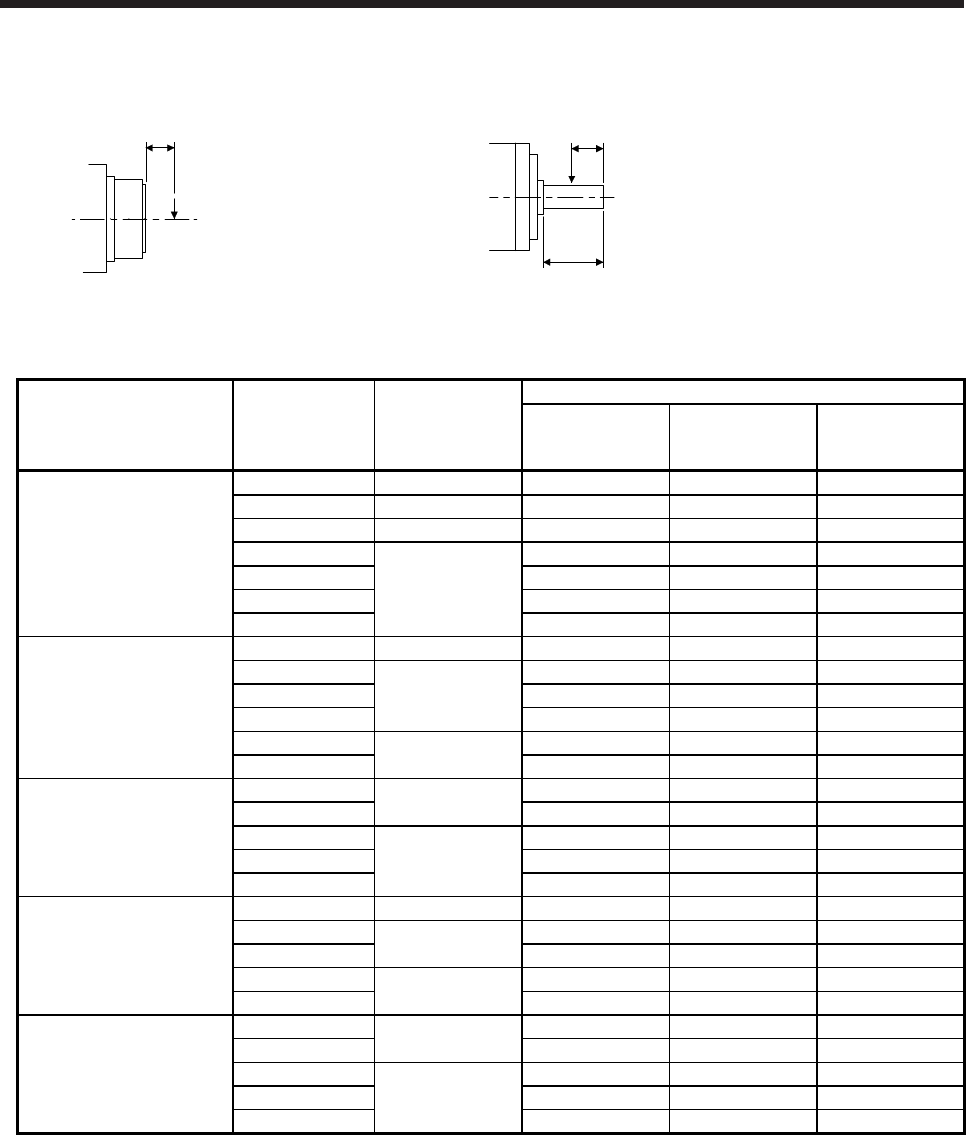
(3) Permissible loads of servo motor shaft
The radial load point of a high precision reducer is as shown below.
L: Distance between reducer
end face and load center
L
Q: Length of axis (Refer to section 6.8.7, 6.8.8.)
Q/2
Q
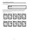
Flange-mounting flange output type for
high precision application (G5)
Flange-mounting shaft output type for
high precision application (G7)
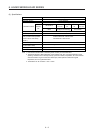
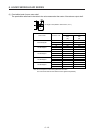
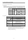
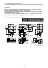
Servo motor Reduction ratio
Reducer model
number
Permissible load (Note)
Radial load point
L [mm]
Permissible radial
load
[N]
Permissible thrust
load
[N]
1/5 11B 17 93 431
1/5 14A 23 177 706
HG-KR053(B)G5
HG-KR053(B)G7
1/9 11B 17 111 514
1/11 23 224 895
1/21
14A
23 272 1087
1/33 23 311 1244
1/45 23 342 1366
1/5 11B 17 93 431
1/5 23 177 706
HG-KR13(B)G5
HG-KR13(B)G7
1/11 14A 23 224 895
1/21 23 272 1087
1/33
20A
32 733 2581
1/45 32 804 2833
1/5
14A
23 177 706
HG-KR23(B)G5
HG-KR23(B)G7
1/11 23 224 895
1/21 32 640 2254
1/33 20A 32 733 2581
1/45 32 804 2833
1/5 14A 23 177 706
HG-KR43(B)G5
HG-KR43(B)G7
1/11
20A
32 527 1856
1/21 32 640 2254
1/33
32A
57 1252 4992
1/45 57 1374 5478
1/5
20A
32 416 1465
HG-KR73(B)G5
HG-KR73(B)G7
1/11 32 527 1856
1/21 57 1094 4359
1/33 32A 57 1252 4992
1/45 57 1374 5478
Note. Do not subject the shaft to load greater than the value.
The value in the table assumes that the load is applied independently.