


7. HG-SR SERIES
7 - 46
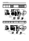
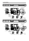
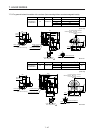
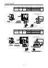
Model Output [kW] Reducer model Reduction ratio Brake static friction torque [N•m] Moment of inertia J [× 10
-4
kg•m
2
] Mass [kg]
HG-SR702BG1
HG-SR7024BG1
7.0 CHVM-6180
1/29
44
202
178
1/35 201
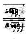
[Unit: mm]
U
W
V
Key
(PE)
Power supply connector
Motor flange direction
Electromagnetic brake
Electromagnetic brake connector
Motor flange direction
Main key
position mark
595.5
□176
96.9
149.1
Caution plate
44
82
Caution plate
Motor plate
Motor plate
Caution plate
13
32121.2
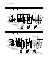
66.5
Power supply
connector
MS3102A32-17P
Electromagnetic brake
connector
CMV1-R2P
Encoder connector
CMV1-R10P
Top
50.9
45.5
Top
176
φ345f8
φ430
22
5
110
100
279
φ370
A
A
110
258
8-φ18
2
2
.
5
°
M12 Screw hole depth 24
Shaft section view AA
22
14
9
φ80h6
(Side view of motor only)
BC41203*
φ
3
9
0
Bottom
Bottom
For reverse rotation command
For forward rotation command
Rotation direction
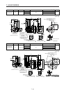
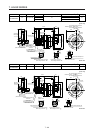
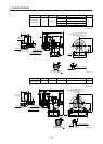
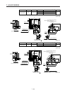
Model Output [kW] Reducer model Reduction ratio Brake static friction torque [N•m] Moment of inertia J [× 10
-4
kg•m
2
] Mass [kg]
HG-SR702BG1
HG-SR7024BG1
7.0 CHVM-6195
1/43
44
277
246
1/59 275
[Unit: mm]
BC41204*
U
W
V
Power supply connector
Motor flange direction
Key
Electromagnetic brake
Electromagnetic brake connector
Motor flange direction
Main key
position mark
210
9
14
25
φ95h6
M20 Screw hole depth 34
φ400f8
φ490
30
6
651.5
145
125
285
1
5
°
12-φ18
320
φ430
□176
96.9
149.1
Caution plate
44
82
Caution plate
Motor plate
Motor plate
Caution
plate
13
32
121.2
66.5
Power supply
connector
MS3102A32-17P
Electromagnetic brake
connector
CMV1-R2P
Encoder connector
CMV1-R10P
Top
A
A
Shaft section view AA
50.9
135
45.5
Top
(Side view of motor only)
(PE)
φ
4
5
0
Bottom
Bottom
For reverse rotation command
For forward rotation command
Rotation direction