


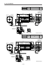

8. HG-JR SERIES
8 - 34
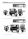
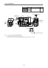
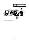
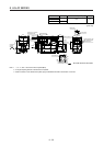
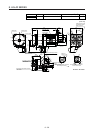
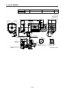
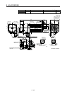
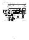
Model Output [kW] Moment of inertia J [× 10
-4
kg•m
2
] Mass [kg]
HG-JR25K1
25
HG-JR25K14
764 165
HG-JR37K1M
37
HG-JR37K1M4
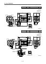
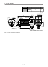
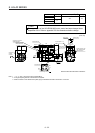
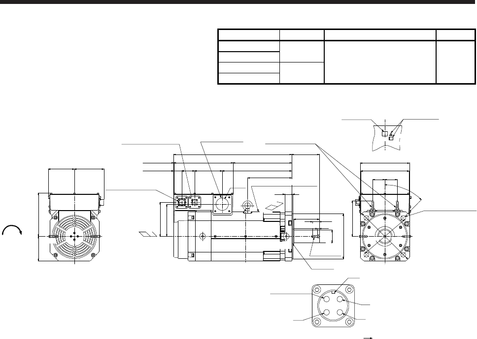
[Unit: mm]
Cooling fan
rotation
d
irection
Caution plate
Motor plate
Top
Intake
□250 (Flange)
Eyebolt (Note 2, 3)
247
4
5
°
φ
2
6
5
φ
3
3
0
62 62
4-φ24 mounting hole
Use hexagon socket
head cap screw.
220125
150133
(Note 1)
*1
140
35 5
600
298300
224
35314065
Approx. 42
φ230h7
Exhaust
Oil seal
33
M12 screw
174
163
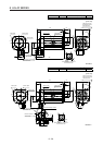
Power lead hole
Encoder connector
MS3102A20-29P
Cooling fan connector
CE05-2A14S-2P
φ63
Approx. 2
BV
BW
Cooling fan connector
Motor flange direction
BC41682* BC41683* BC43645* BC43646*
BU
To be left open
Key
181
130
(Note 1)
*1,*2
(Note 1)
*3,*4
φ65m6
(Note 1)
*3
(Note 1)
*4
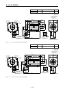
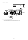
Motor plate/Caution plate
Top
Bottom
Approx. 8
Bottom
Top
Bottom
(Note 1)
*2
Note 1. *1, *2, *3, and *4 are screw hole for eyebolt (M12).
2.
A
n angle adjusting washer is inserted into the eyebolt.
3. When the motor is used without the eyebolt, plug the threaded hole with a bolt of M12 × 20 or less.