


8. HG-JR SERIES
8 - 45
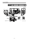
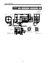
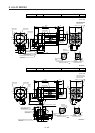
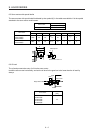
Model Output [kW] Brake static friction torque [N•m] Moment of inertia J [× 10
-4
kg•m
2
] Mass [kg]
HG-JR601B
6
HG-JR6014B
126 196 65
HG-JR701MB
7
HG-JR701M4B
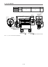
[Unit: mm]
U
(PE)
W
V
B
C
A
D
Power connector
Motor flange direction
BC43510* BC43511* BC43512* BC43513*
Key
B
A
Electromagnetic brake connector
Motor flange direction
Electromagnetic brake
Caution plate
Caution plate
Motor plate
Bottom
Top
Bottom
Top
(Note)
*2
(Note)
*1
(Note)
*4
(Note)
*3
Key
Top
Bottom
Top
φ200h7
225.5
25
φ42h6
79
420
85372
(Note) *1,*2
Motor plate
(Opposite side)
130
136.2
19.5
Power connector
MS3102A32-17P
Electromagnetic brake connector
MS3102A10SL-4P
Encoder connector
MS3102A20-29P
Caution plate
81
40
82
4 54
171.1
□220
4
5
°
3
7
.
5
°
2-M8 screw
φ
2
7
0
φ
2
5
0
φ
2
3
5
4-φ13.5 mounting hole
Use hexagon socket
head cap screw.
Oil seal
M8 screw
32
(Note) *3,*4
Bottom
Note. *1, *2, *3, and *4 are screw hole for eyebolt (M10).
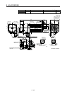
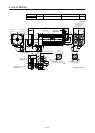
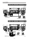
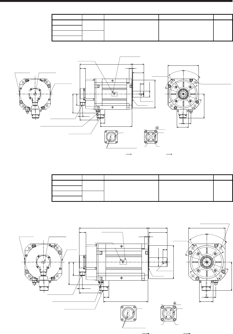
Model Output [kW] Brake static friction torque [N•m] Moment of inertia J [× 10
-4
kg•m
2
] Mass [kg]
HG-JR801B
8
126 240 74
HG-JR8014B
HG-JR11K1MB
11
HG-JR11K1M4B
[Unit: mm]
φ
200h7
27
φ55m6
110
116
4
20
412
40
32
265.5
130
136.2
81
19.5
Power supply connector
MS3102A32-17P
Electromagnetic brake connector
MS3102A10SL-4P
Encoder connector
MS3102A20-29P
82
4 54
171.1
□
220
4
5
°
3
7
.
5
°
2-M8 screw
φ
2
7
0
φ
2
5
0
φ
23
5
4-
φ
13.5 mounting hole
Use hexagon socket
head cap screw.
U
W
V
B
C
A
D
Power supply connector
Motor flange direction
Key
B
A
Motor flange direction
Electromagnetic
brake
Caution
plate
Caution plateMotor plate
Caution plate
M10 screw
Oil seal
Motor plate
(Opposite side)
Key
(PE)
(Note) *3,*4
(Note) *1,*2
(Note)
*3
(Note)
*2
(Note)
*1
(Note)
*4
Bottom
Top
Top
Bottom
T
op
Bottom
Top
Electromagnetic brake connector
BC42635A BC42646A BC43506* BC43507*
Bottom
Note. *1, *2, *3, and *4 are screw hole for eyebolt (M10).