


APPENDIX
App. - 20
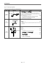
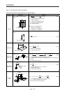
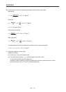
App. 5.7 Load moment of inertia equations
Typical load moment of inertia equations is indicated below.
Type Mechanism Equation
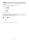
Cylinder
Axis of rotation is on the cylinder
center
A
xis of rotation
L
D
1
D
2
J
L0
=
32
• L
•
(D
1
- D
2
)
44
=
8
W
•
(D
1
+ D
2
)
22
······································ (5.22)
ρ: Cylinder material density [kg/cm
3
]
L: Cylinder length [cm]
D
1
: Cylinder outside diameter [cm]
D
2
: Cylinder inside diameter [cm]
W: Cylinder mass [kg]
Reference data: material density
Iron: 7.8 • 10
-3
[kg/cm
3
]
Aluminum: 2.7 • 10
-3
[kg/cm
3
]
Copper: 8.96 • 10
-3
[kg/cm
3
]
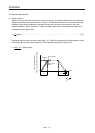
Axis of rotation is on the cylinder
center
Axis of rotation
D
R
J
L0
=
8
W
• (D
2
+ 8R
2
) ·································································· (5.23)
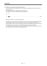
Square block
A
xis of rotation
R
a
a
b
b
J
L0
= W •
3
a
2
+ b
2
+ R
2
····························································· (5.24)
W: Square block mass [kg]
a, b, R: Left diagram [cm]
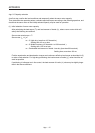
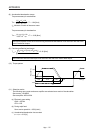
Object which
moves linearly
Servo motor
V
W
N
J
L
= W •
V
2
600 •
= W •
• N
•
2•
1
10
V
2
= W •
S
2
20 •
··········· (5.25)
V: Speed of object which moves linearly [mm/min]
∆S: Travel distance of object moving linearly per servo motor revolution
[mm/rev]
W: Square block mass [kg]
Object that is
hung with pulley
Servo motor
W
D
J
L
= W •
2
2
D
+ J
P
····································································· (5.26)
J
P
: Pulley moment of inertia [× 10
-4
kg•m
2
]
D: Pulley diameter [cm]
W: Square block mass [kg]
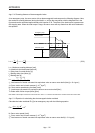
Converted
load
Load A
J
A
J
31
N
3
J
21
J
11
J
22
N
2
N
1
Load B
J
B
J
L
= J
11
+ (J
21
+ J
22
+ J
A
) •
2
N
1
N
2
+ (J
31
+ J
B
) •
2
N
1
N
3
························ (5.27)
J
A
, J
B
: Moment of inertia of load A, B [× 10
-4
kg•m
2
]
J
11
to J
31
: Moment of inertia [× 10
-4
kg•m
2
]
N
1
to N
3
: Speed of each shaft [r/min]