


4. CONNECTION OF SERVO AMPLIFIER AND SERVO MOTOR
4 - 5
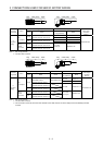
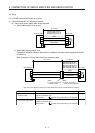
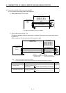
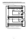
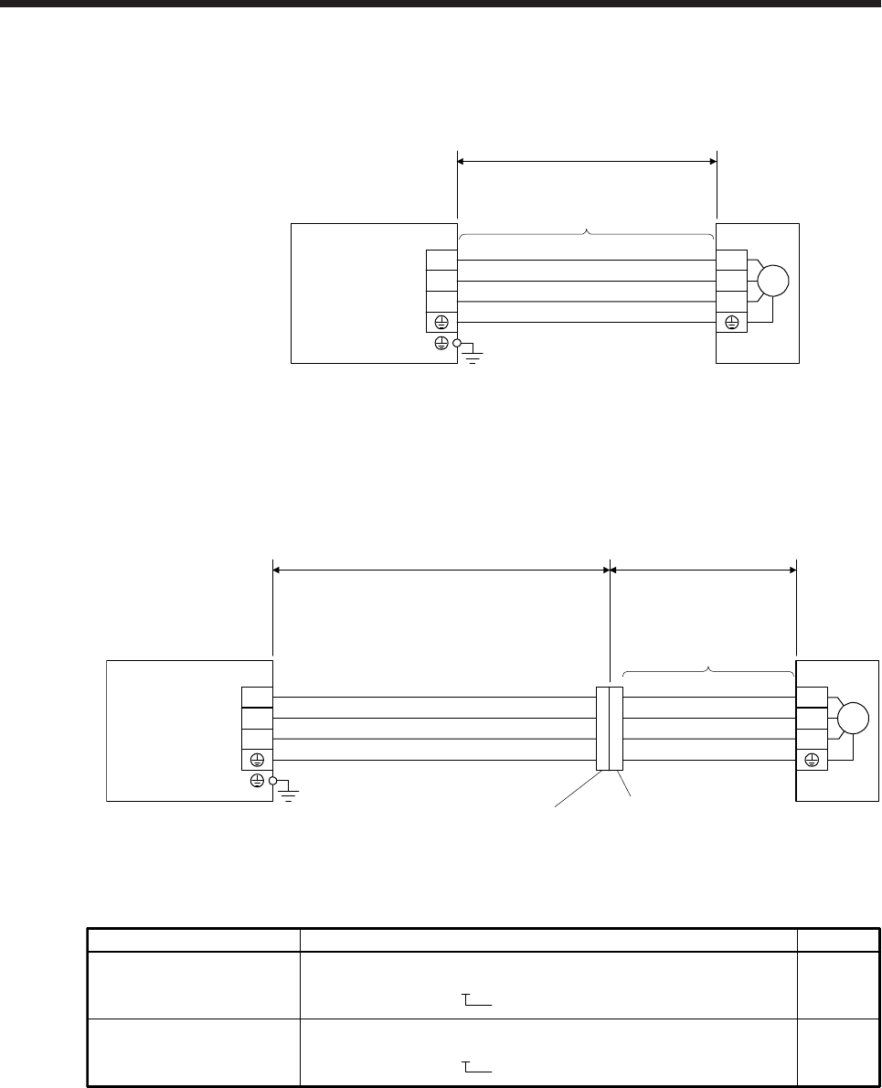
(2) Connection with MR-J4 multi-axis servo amplifier
(a) Servo motor power supply cable wiring diagrams
1) When cable length is 10 m or less
CNP3A/CNP3B/
CNP3C
(Note)
(Red)
(White)
(Black)
(Green/yellow)
U
V
W
U
V
W
Servo motorServo amplifier
10 m or less
M
MR-PWS1CBL_M-A1-L
MR-PWS1CBL_M-A2-L
MR-PWS1CBL_M-A1-H
MR-PWS1CBL_M-A2-H
Note. CNP3 is for the MR-J4 3-axis servo amplifier.
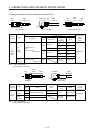
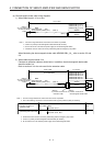
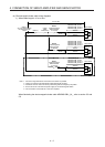
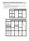
2) When cable length exceeds 10 m
Fabricate an extension cable as shown below. In addition, the motor power supply cable should
be within 2 m.
Refer to section 4.3 for the wire used for the extension cable.
(Note 2)
b) Junction connector for
motor power supply cable
(Note 2)
a) Junction connector for
extension cable
MR-PWS1CBL2M-A1-L
MR-PWS1CBL2M-A2-L
MR-PWS1CBL2M-A1-H
MR-PWS1CBL2M-A2-H
MR-PWS2CBL03M-A1-L
MR-PWS2CBL03M-A2-L
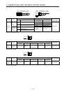
(Red)
(White)
(Black)
(Green/yellow)
Extension cable
50 m or less 2 m or less
CNP3A/CNP3B/
CNP3C
(Note 1)
U
V
W
U
V
W
Servo motorServo amplifier
M
Note 1. CNP3 is for the MR-J4 3-axis servo amplifier.
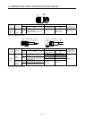
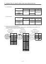
2. Use of the following connectors is recommended when ingress protection (IP65) is necessary.
Connector: RM15WTPZ-4P(71)
Cord clamp: JR13WCC-5(72)
(Hirose Electric)
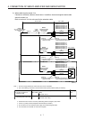
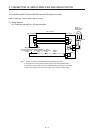
b)
Junction connector for
motor power supply cable
a) Junction connector for
extension cable
Junction connector
Connector: RM15WTJZ-4S(71)
Cord clamp: JR13WCC-8(72)
(Hirose Electric)
Numeral changes depending on the cable OD.
Numeral changes depending on the cable OD.
Description IP rating
IP65
IP65