


4. CONNECTION OF SERVO AMPLIFIER AND SERVO MOTOR
4 - 13
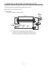
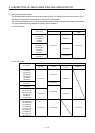
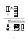
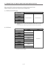
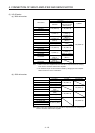
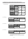
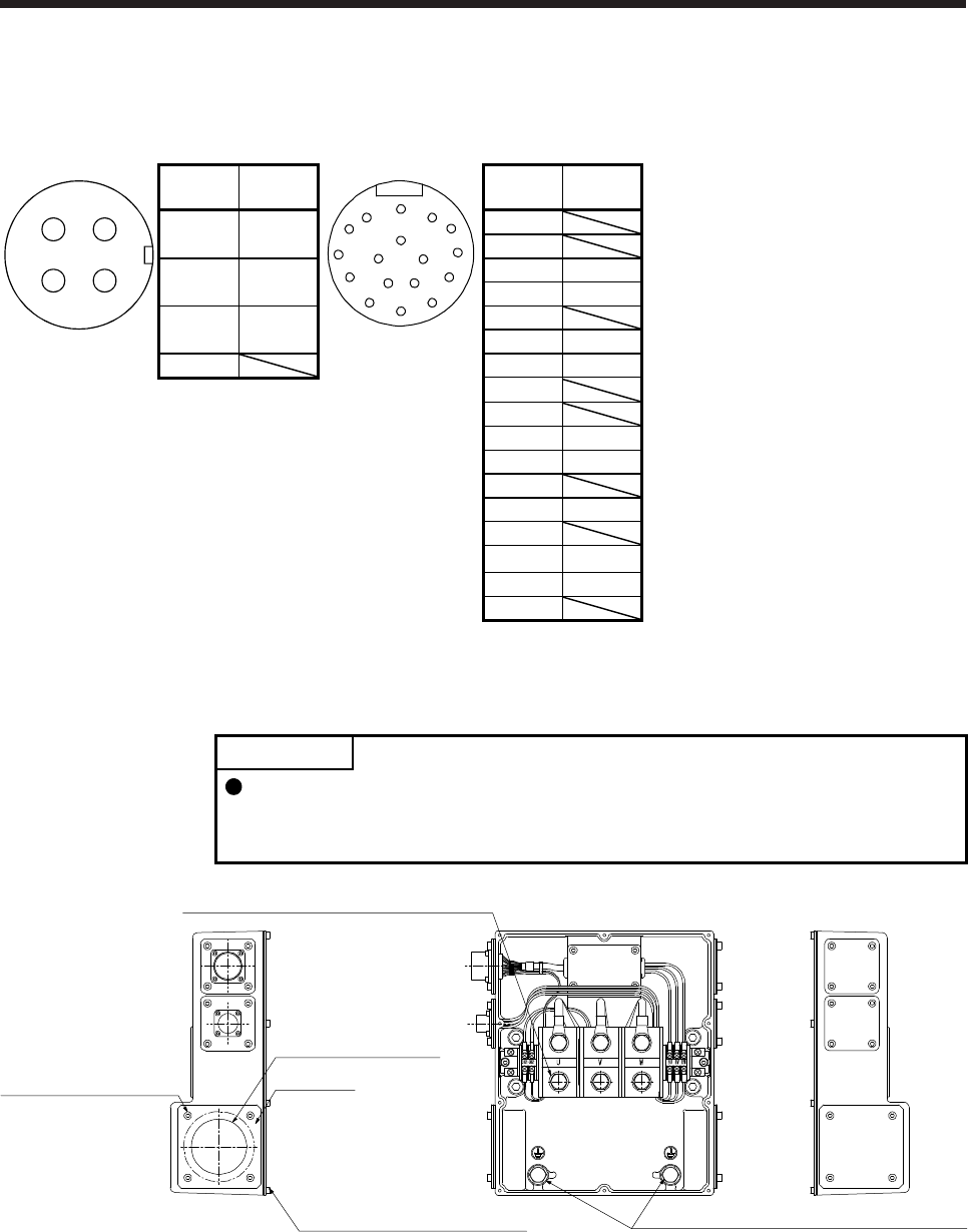
Connector K
Cooling fan connector
CE05-2A14S-2P
Connector L
Encoder connector
MS3102A20-29P
CD
AB
Terminal
No.
Signal
A
N
G
S R
T P
HF
J
E
K
D
L
M
B
C
Pin Signal
A
BU
(Note)
A
B
B
BV
(Note)
C MR
D MRR
C
BW
(Note)
E
F BAT
D G LG
Note. Refer to the
chapter of the
servo motor
series for the
specifications of
the power
supplied to the
cooling fan.
H
J
K THM1
L THM2
M
N SHD
P
R LG
S P5
T
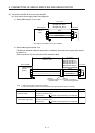
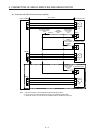
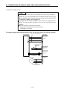
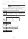
(4) Terminal box inside
HG-JR22K1M(4) to HG-JR37K1M(4)/HG-JR45K1M4/HG-JR55K1M4/HG-JR15K1(4) to HG-JR37K1(4)
POINT
The terminal box of the HG-JR22K1M(4) servo motor has been changed since
September 2014. Refer to appendix 9 for the terminal box detail diagram before
change.
Terminal box lid: M4 screw (10)
Keep plate
Power lead hole (Note)
Keep plate: M5 screw (4)
Power supply terminal block: M10 screw (3)
Protective earth (PE) terminal: M10 screw (2)
Note. Provide measures to prevent oil, water, dust and dirt from entering the servo motor through the power lead hole.