


4. CONNECTION OF SERVO AMPLIFIER AND SERVO MOTOR
4 - 15
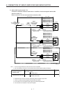
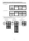
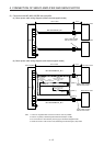
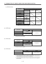
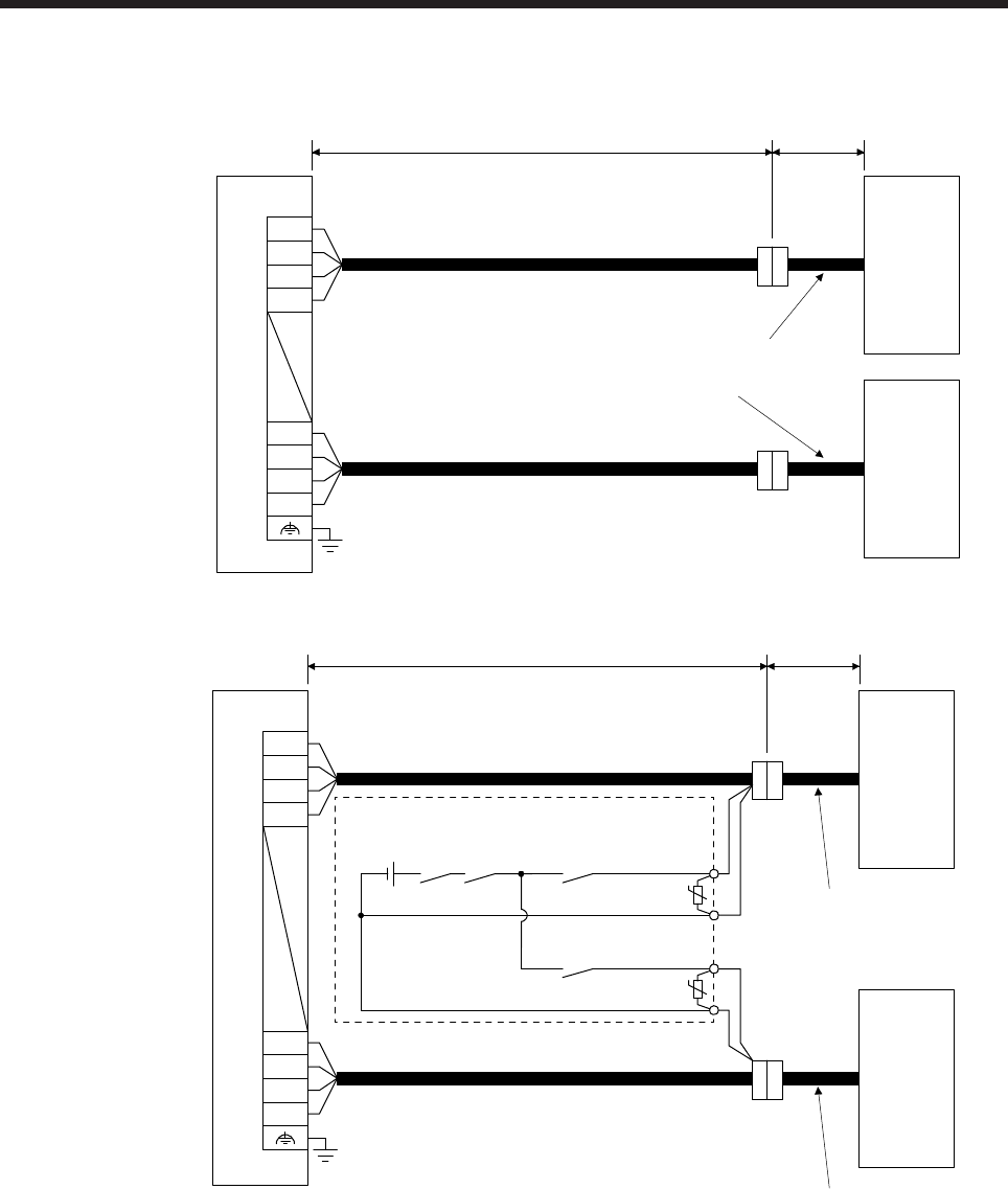
(2) Connection with MR-J4W2-0303B6 servo amplifier
(a) Motor power cable wiring diagram (without electromagnetic brake)
Power cable supplied
with the servo motor
B-axis servo motor
MR-J4W03PWCBL_M-H
CNP1
A-axis servo motorServo amplifier
30 m or less 0.2 m
MR-J4W03PWCBL_M-H
U1
V1
W1
E1
U2
V2
W2
E2
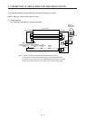
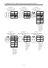
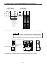
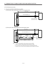
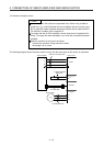
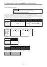
(b) Motor power cable wiring diagram (with electromagnetic brake)
Power cable supplied
with the servo motor
CNP1
A-axis servo motorServo amplifier
30 m or less 0.2 m
MR-J4W03PWBRCBL_M-H
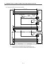
(Note 3)
24 V DC power
supply for
electromagnetic
brake
MBR-A
(Electromagnetic brake
interlock for A-axis)
RA2
U
CALM
(AND malfunction)
(Note 1)
Fabricate it.
(Note 3)
MBR-B
(Electromagnetic brake
interlock for B-axis)
RA4
U
(Note 1)
(Note 3)
Power cable supplied
with the servo motor
B-axis servo motor
MR-J4W03PWBRCBL_M-H
(Note 2)
(Note 2)
U1
V1
W1
E1
U2
V2
W2
E2
(Note 4)
Note 1. Connect a surge absorber as close to the servo motor as possible.
2. There is no polarity in electromagnetic brake terminals (B1 and B2).
3. Do not use the 24 V DC interface power supply for the electromagnetic brake.
4. Create the circuit in order to shut off by interlocking with the emergency stop switch.