


4. CONNECTION OF SERVO AMPLIFIER AND SERVO MOTOR
4 - 20
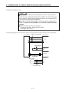
4.4 Servo amplifier terminal section
POINT
For the sizes of wires used for wiring, refer to section 4.3.
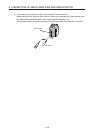
The drive unit do not have these connectors.
To wire to the servo amplifier, use connectors packed with the amplifier or optional connectors.
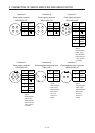
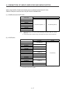
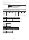
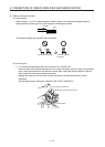
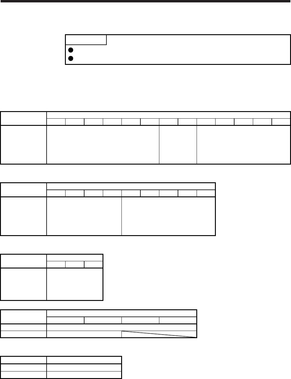
The following table shows the connectors to be connected to the servo amplifiers. The numbers in the rated
output field of the table indicate the symbol filling the underline "_" in the servo amplifier model. For details of
the connectors, refer to (1) of this section. For wiring, refer to (2) of this section.
Servo amplifier
Rated output
10 20 40 60 70 100 200 350 500 700 11K 15K 22K
MR-J4-_A
MR-J4-_A-RJ
MR-J4-_B
MR-J4-_B-RJ
MR-J4-_B-RJ010
MR-J4-_B-RJ020
Connector A Connector B None (terminal block) (Note)
Note. For details on the terminal block, refer to each servo amplifier instruction manual.
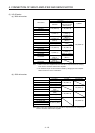
Servo amplifier
Rated output
60 100 200 350 500 700 11K 15K 22K
MR-J4-_A4
MR-J4-_A4-RJ
MR-J4-_B4
MR-J4-_B4-RJ
MR-J4-_B4-RJ010
MR-J4-_B4-RJ020
Connector D None (terminal block) (Note)
Note. For details on the terminal block, refer to each servo amplifier instruction manual.
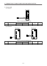
Servo amplifier
Rated output
10 20 40
MR-J4-_A1
MR-J4-_A1-RJ
MR-J4-_B1
MR-J4-_B1-RJ
MR-J4-_B1-RJ020
Connector A
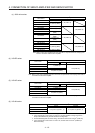
Servo amplifier
Rated output (Note)
22 (222) 44 (444) 77 1010
MR-J4W2-_B Connector C
MR-J4W3-_B Connector C
Note. The numbers in parentheses are for the MR-J4 3-axis servo amplifier.
Servo amplifier Connector
MR-J4-03A6(-RJ) Connector E
MR-J4W2-0303B6 Connector F