


5. WIRING OPTION
5 - 14
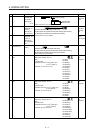
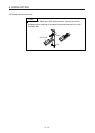
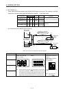
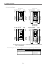
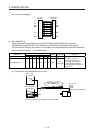
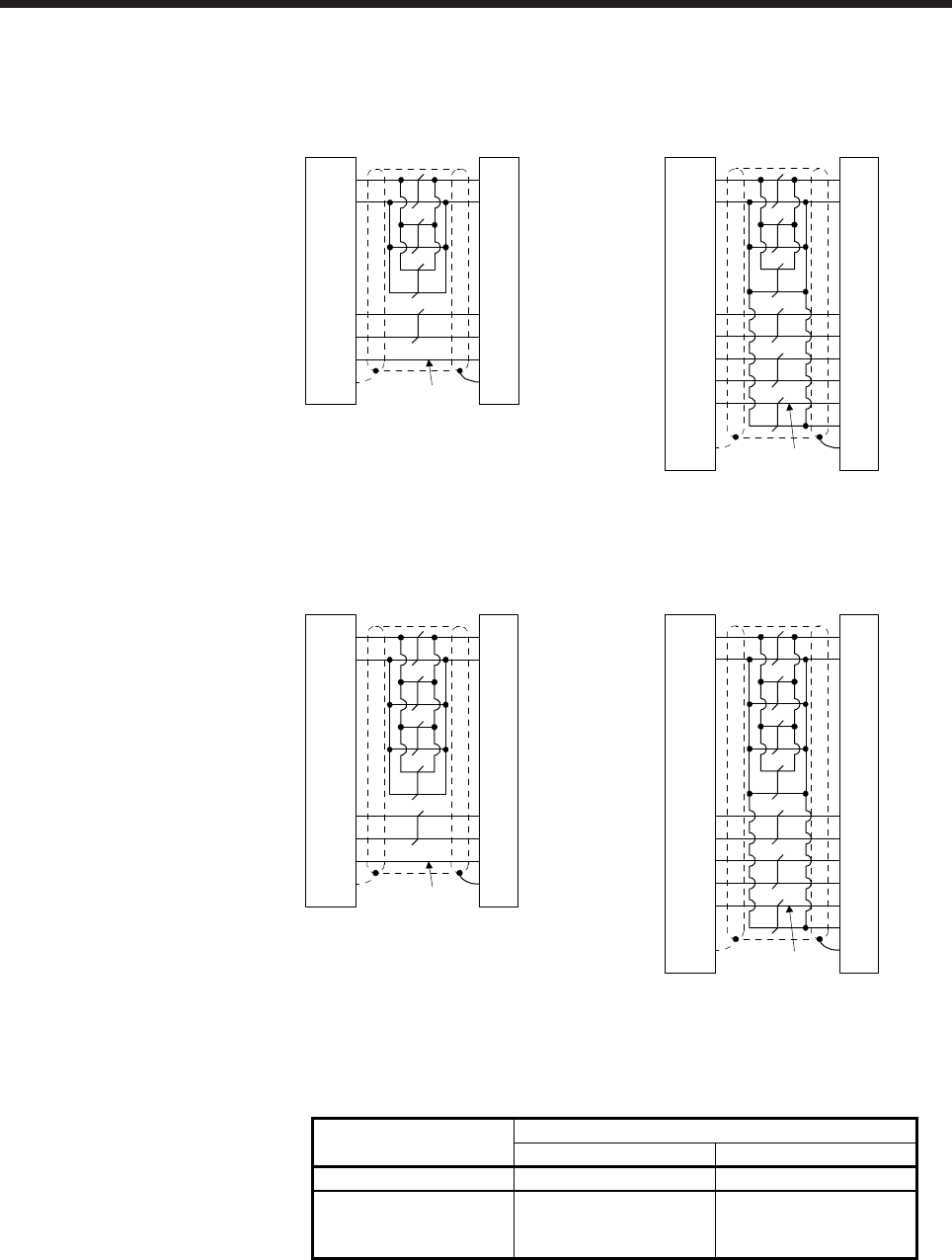
(b) Internal wiring diagram
MR-EKCBL20M-L
CN2, CN2A, CN2B, and
CN2C side connector
Junction
connector
(Note)
P5
LG
1
2
MR
MRR
3
4
3
7
9
SD
Plate
1
2
8
9
LG
MR
MRR
SHD
P5
BATBAT
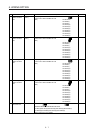
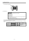
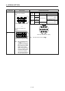
MR-EKCBL30M-L
(Note)
P5
LG
1
2
MR
MRR
3
4
MDR 8 5
3
7
4
MD
7
9
SD
Plate
1
2
8
9
LG
MR
MRR
MDR
MD
SHD
P5
6 CONT
BATBAT
CN2, CN2A, CN2B, and
CN2C side connector
Junction
connector
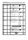
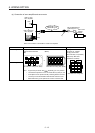
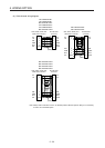
MR-EKCBL20M-H
(Note)
P5
LG
1
2
MR
MRR
3
4
3
7
9
SD
Plate
1
2
8
9
LG
MR
MRR
SHD
P5
BATBAT
CN2, CN2A, CN2B, and
CN2C side connector
Junction
connector
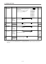
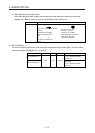
MR-EKCBL30M-H
MR-EKCBL40M-H
MR-EKCBL50M-H
CN2, CN2A, CN2B, and
CN2C side connector
Junction
connector
(Note)
P5
LG
1
2
MR
MRR
3
4
MDR
85
3
7
4
MD
7
9
SD
Plate
1
2
8
9
LG
MR
MRR
MDR
MD
SHD
P5
6
CONT
BATBAT
Note.
A
lways make connection for use in an absolute position detection system. Wiring is not necessary
for use in an incremental system.
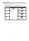
When fabricating the cable, use the wiring diagram corresponding to the length indicated below.
Cable bending life
Applicable wiring diagram
Less than 30 m 30 m to 50 m
Standard MR-EKCBL20M-L MR-EKCBL30M-L
Long bending life MR-EKCBL20M-H MR-EKCBL30M-H
MR-EKCBL40M-H
MR-EKCBL50M-H