


5. WIRING OPTION
5 - 26
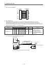
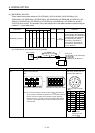
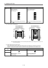
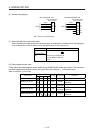
Cable model 1) CN2, CN2A, and CN2B-side connector 2) Encoder-side connector
MR-J3W03ENCBL_
M-A-H
Receptacle housing: 1-1827862-5
Contact: 1827587-2
Crimping tool: 1762846-1
(TE Connectivity)
5B
4B
BAT
LG
3B
2B
1B
MRR
5A
4A
SD
P5
3A
2A
1A
MR
Tab housing: J21DPM-10V-KX
Contact: SJ2M-01GF-M1.0N
Crimping tool: YRS-8861
(JST)
5A
4A
BAT
LG
3A
2A
1A
MRR
5B
4B
SHD
P5
3B
2B
1B
MR
Note. Do not connect anything to the pins shown as
.
Note.Do not connect anything to the pins shown as
.
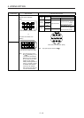
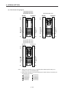
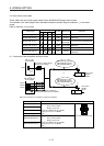
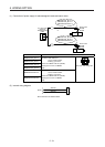
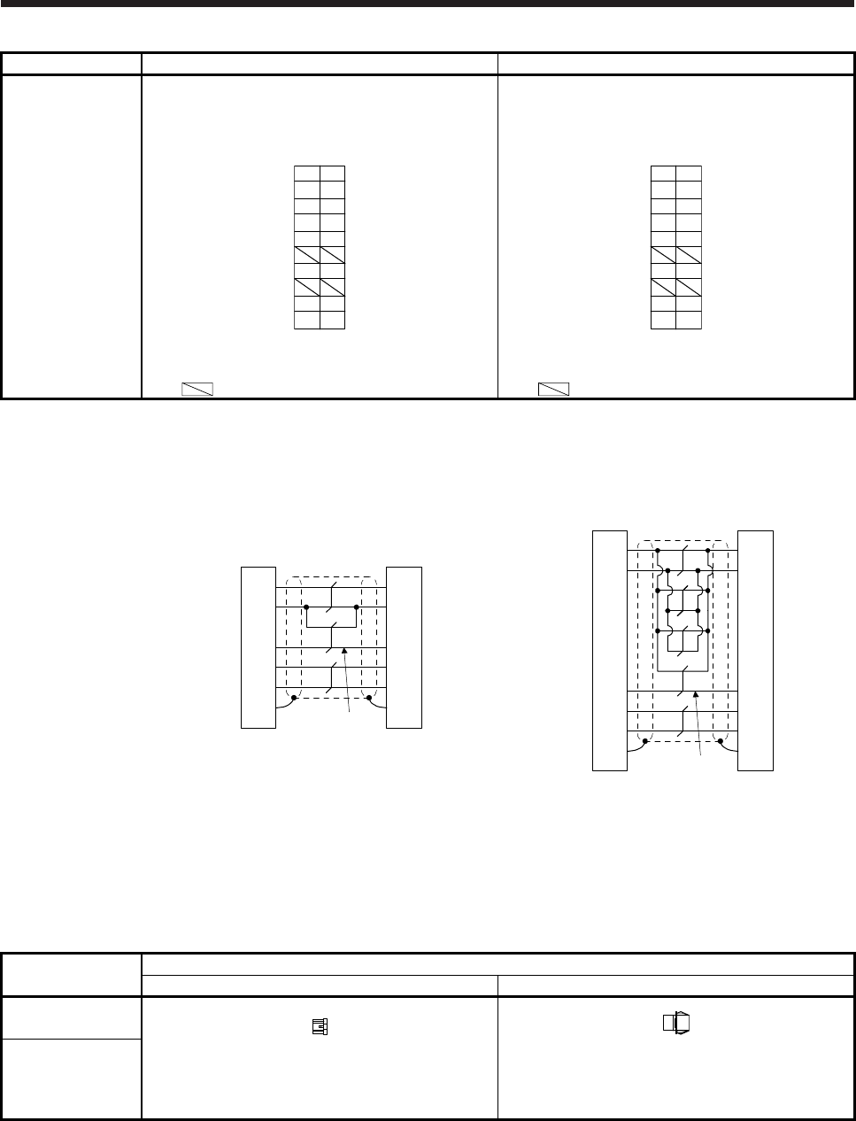
(b) Cable internal wiring diagram
(Note)
P5
LG
MR
MRR
5A
4B
CN2, CN2A, and
CN2B-side connector
Encoder-side
connector
1B
1A
4A
MR-J3W03ENCBL1M-A-H
MR-J3W03ENCBL2M-A-H
MR-J3W03ENCBL5M-A-H
MR-J3W03ENCBL10M-A-H
LG
MR
MRR
P5
BATBAT
SD 5B SHD
5B
4A
1A
1B
4B
5A
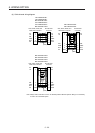
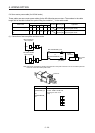
(Note)
P5
LG
MR
MRR
5A
4B
CN2, CN2A, and
CN2B-side connector
Encoder-side
connector
1B
1A
4A
MR-J3W03ENCBL20M-A-H
MR-J3W03ENCBL30M-A-H
LG
MR
MRR
P5
BATBAT
SD 5B SHD
5B
4A
1A
1B
4B
5A
Note.
A
lways make connection for use in an absolute position detection system. Wiring is not necessary for use
in an incremental system.
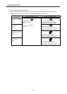
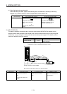
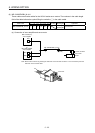
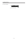
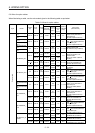
(c) When fabricating the encoder cable
When fabricating the cable, prepare the following parts, and fabricate it according to the wiring
diagram in (8) (b) of this section. Refer to section 5.6 for the specifications of the cable to use.
Connector set
model
Description
CN2, CN2A, and CN2B side connector Encoder-side connector
MR-J3W03CN2-2P
Receptacle housing: 1-1827862-5
Contact: 1827587-2
(TE Connectivity)
Tab housing: J21DPM-10V-KX
Contact: SJ2M-01GF-M1.0N
(JST)
MR-J3W03CN2-20P