


7. HG-SR SERIES
7 - 15
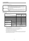
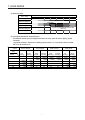
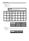
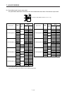
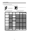
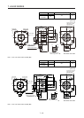
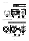
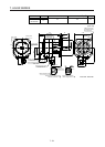
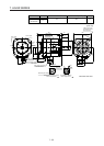
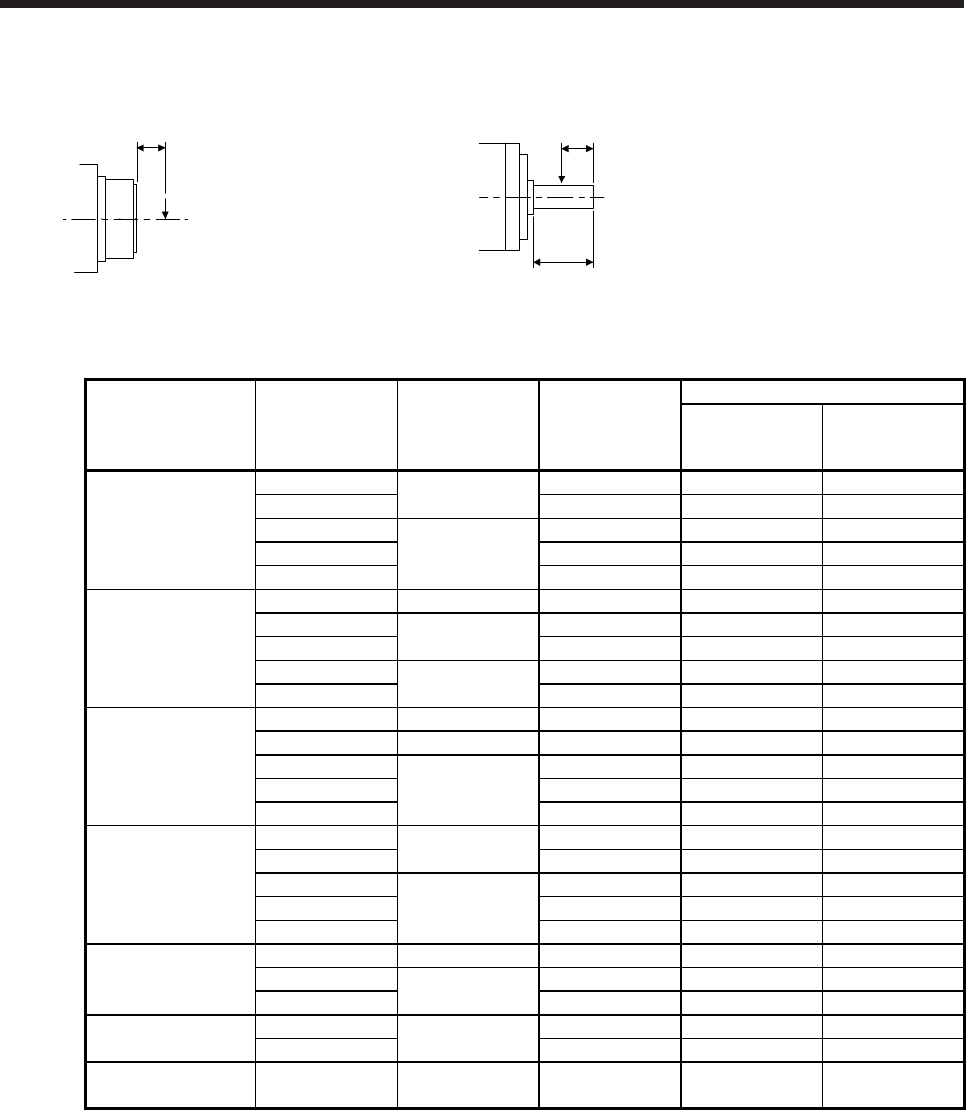
(3) Permissible loads of servo motor shaft
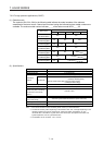
The radial load point of a high precision reducer is as shown below.
L: Distance between reducer
end face and load center
L
Q: Length of axis (Refer to section 7.7.9, 7.7.10.)
Q/2
Q
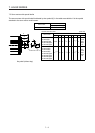
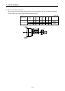
Flange-mounting flange output type for
high precision application (G5)
Flange-mounting shaft output type for
high precision application (G7)
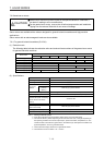
Servo motor Reduction ratio
Reducer model
number
Radial load point
L [mm]
Permissible load (Note)
Permissible radial
load
[N]
Permissible thrust
load
[N]
HG-SR52(4)(B)G5
HG-SR52(4)(B)G7
1/5
20A
32 416 1465
1/11 32 527 1856
1/21
32A
57 1094 4359
1/33 57 1252 4992
1/45 57 1374 5478
HG-SR102(4)(B)G5
HG-SR102(4)(B)G7
1/5 20A 32 416 1465
1/11
32A
57 901 3590
1/21 57 1094 4359
1/33
50A
62 2929 10130
1/45 62 3215 11117
HG-SR152(4)(B)G5
HG-SR152(4)(B)G7
1/5 20A 32 416 1465
1/11 32A 57 901 3590
1/21
50A
62 2558 8845
1/33 62 2929 10130
1/45 62 3215 11117
HG-SR202(4)(B)G5
HG-SR202(4)(B)G7
1/5
32A
57 711 2834
1/11 57 901 3590
1/21
50A
62 2558 8845
1/33 62 2929 10130
1/45 62 3215 11117
HG-SR352(4)(B)G5
HG-SR352(4)(B)G7
1/5 32A 57 711 2834
1/11
50A
62 2107 7285
1/21 62 2558 8845
HG-SR502(4)(B)G5
HG-SR502(4)(B)G7
1/5
50A
62 1663 5751
1/11 62 2107 7285
HG-SR702(4)(B)G5
HG-SR702(4)(B)G7
1/5 50A 62 1663 5751
Note. Do not subject the shaft to load greater than the value.
The value in the table assumes that the load is applied independently.