


7. HG-SR SERIES
7 - 79
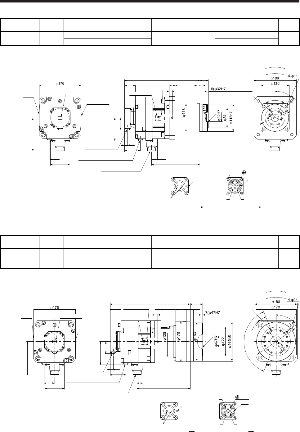
Model
Output
[kW]
Reducer model
Reduction
ratio
Brake static friction torque
[N•m]
Moment of inertia J
[× 10
-4
kg•m
2
]
Mass
[kg]
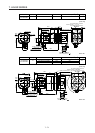
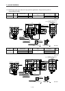
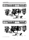
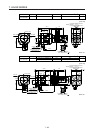
HG-SR202BG5
HG-SR2024BG5
2.0
HGP-32A-05-F0PBZI-S 1/5
44
61.1
25
HGP-32A-11-F0PBZJ-S 1/11 60.9
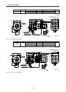
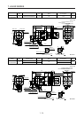
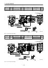
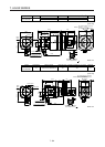
[Unit: mm]
Bottom
Top
Top
Bottom
317
45.5
Caution plate
Motor plate
(Opposite side)
24.8
203.8
50.9
13
Encoder connector
CMV1-R10P
Power supply connector
MS3102A22-22P
Bottom
Top
Bottom
Top
96.9
Electromagnetic brake connector
CMV1-R2P
66.5
44
25 91
13
12.5
13
140.9
For reverse rotation command
For forward rotation command
Rotation direction
82
4
5
°
effective range)
C0.5
Motor
plate
Caution plate
6-M8 Screw hole depth 12
U
W
V
Power supply connector
Motor flange direction
Key
Electromagnetic brake
Electromagnetic brake connector
Motor flange direction
Main key
position mark
BC41233*
(PE)
35
+0.4
- 0.5
(Note)*
6
0
°
Caution plate
Note. * is a screw hole for eyebolt (M8).
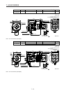
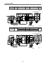
Model
Output
[kW]
Reducer model
Reduction
ratio
Brake static friction torque
[N•m]
Moment of inertia J
[× 10
-4
kg•m
2
]
Mass
[kg]
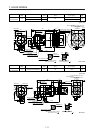
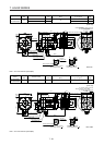
HG-SR202BG5
HG-SR2024BG5
2.0
HPG-50A-21-F0BBDF-S 1/21
44
62.9
35
HPG-50A-33-F0BBDF-S 1/33 61.9
HPG-50A-45-F0BBDF-S 1/45 61.9
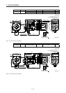
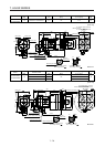
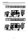
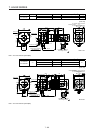
[Unit: mm]
Motor
plate
Caution plate
Bottom
Top
Top
Bottom
337
45.5
Caution plate
Motor plate
(Opposite side)
24.8
223.8
50.9
13
Encoder connector
CMV1-R10P
Power supply connector
MS3102A22-22P
Bottom
Top
Bottom
Top
96.9
Electromagnetic brake connector
CMV1-R2P
66.5
44
U
W
V
Power supply connector
Motor flange direction
Key
Electromagnetic brake
Electromagnetic brake connector
Motor flange direction
25 63 45 16
12.5
140.9
Main key
position mark
For reverse rotation command
For forward rotation command
Rotation direction
82
4
5
°
6×22.5°(=135°)
2
2
.
5
°
14-M8 Screw hole depth 12
effective range)
13
BC41234*
(PE)
53
+0.5
- 0.8
(Note)*
C
0.5
Caution plate
Note. * is a screw hole for eyebolt (M8).