


9. HG-RR SERIES
9 - 3
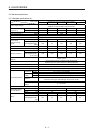
Note 1. When the power supply voltage drops, the output and the rated speed cannot be guaranteed.
2. If the load to motor inertia ratio exceeds the indicated value, contact your local sales office.
3. Except for the shaft-through portion. IP classifies the degrees of protection provided against the intrusion of solid objects and
water in electrical enclosures.
4. In the environment where the servo motor is exposed to oil mist, oil, or water, the servo motor of the standard specifications
may not be usable. Please contact your local sales office.
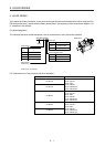
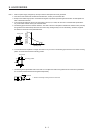
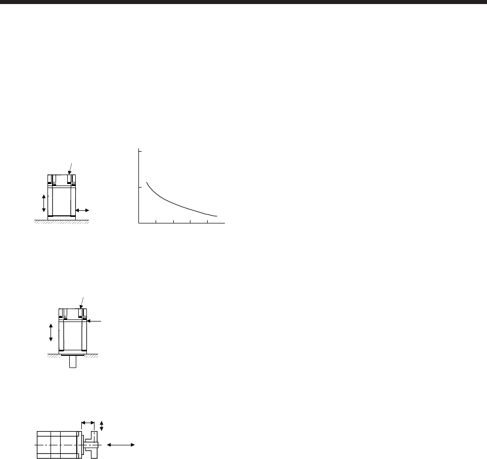
5. The following figure shows the vibration directions. The value is the one at the part that indicates the maximum value (normally
the opposite to load-side bracket). When the servo motor stops, fretting is likely to occur at the bearing. Therefore, suppress
the vibration to about half of the permissible value.
Y
X
Servo motor
Vibration
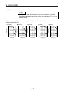
Speed [r/min]
0 1000200030004000
10
100
1000
4500
Vibration amplitude
(both amplitudes)
[μm]
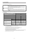
6. V10 indicates that the amplitude of a single servo motor is 10 μm or less. The following figure shows the servo motor mounting
position for measurement and the measuring position.
Servo motor
Top
Bottom
Measuring position
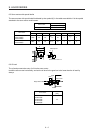
7. The following shows permissible load for the shaft. Do not subject the shaft to load greater than the value in the specifications
list. The value assumes that the load is applied independently.
L
Radial load
Thrust load
L: Distance from flange mounting surface to load center