


APPENDIX
App. - 19
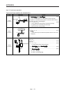
App. 5.6 Load torque equations
Typical load torque equations are indicated below.
Type Mechanism Equation
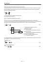
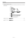
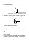
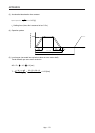
Linear
movement
Servo moto
r
F
C
Z
2
Z
1
F
G
W
T
L
=
F
2 • 10
3
•
•
N
V
=
SF•
2 • 10
3
•
····································· (5.15)
F: Force in the axial direction of the machine in linear motion [N]
F in equation 5.15 is obtained with equation 5.16 when the table is moved,
for example, as shown in the left diagram.
F = F
c
+ µ • (W • g + F
G
) ···························································· (5.16)
F
c
: Force applied in the axial direction of the moving part [N]
F
G
: Tightening force of the table guide surface [N]
W: Full mass of the moving part [kg]
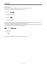
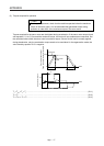
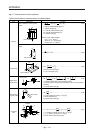
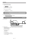
Rotary
movement
Servo motor
Z
1
Z
2
T
L0
T
L
=
n
1
•
1
• T
L0
+ T
F
·································································· (5.17)
T
F
: Load friction torque converted into equivalent value on servo motor
shaft [N•m]
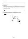
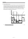
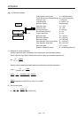
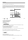
Vertical
movement
Servo motor
Counterweight
1/n
Guide
Load
W
2
W
1
During rise
T
L
= T
U
+ T
F
·········································································· (5.18)
During fall
T
L
= -T
U
• η
2
+ T
F
···································································· (5.19)
T
F
: Friction torque of the moving part [N•m]
T
U
=
(W
1
- W
2
)• g
2 • 10
3
•
•
N
V
=
2 • 10
3
•
S(W
1
- W
2
)• g•
····························· (5.20)
T
F
=
2 • 10
3
•
S(W
1
- W
2
)• g•
························································· (5.21)
W
1
: Mass of load [kg]
W
2
: Mass of counterweight [kg]