


APPENDIX
App. - 35
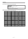
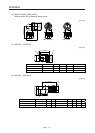
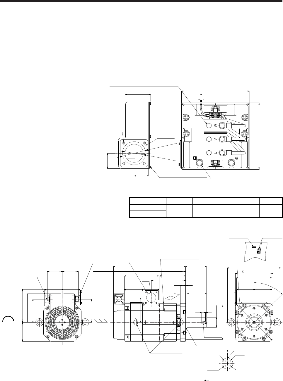
App. 9 HG-JR22K1M(4) appearance change
The appearance of the HG-JR22K1M(4) servo motor has been changed since September 2014. The
following shows the terminal box detail diagram and dimensions before change.
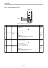
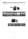
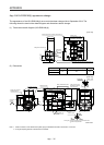
(1) Terminal box detail diagram (HG-JR22K1M(4))
[Unit: mm]
Approx. 235
Approx. 230
Approx. 88.6
Protective earth (PE) terminal: M10 screw (2)
Power supply terminal block: M10 screw (3)
Terminal box lid: M4 screw (8)
Approx. 52.5
φ
6
3
h
o
l
e
φ
8
0
h
o
l
e
T
e
r
m
i
n
a
l
b
o
x
s
i
d
e
Keep plate
K
e
e
p
p
l
a
t
e
s
i
d
e
Keep plate: M5 screw (4)
Approx. 50.5
Connected to the
encoder connector
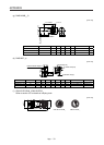
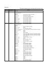
(2) Dimensions
Model Output [kW] Moment of inertia J [× 10
-4
kg•m
2
] Mass [kg]
HG-JR22K1M
22 489 120
HG-JR22K1M4
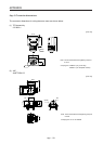
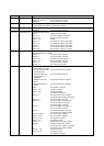
[Unit: mm]
Caution plate
Motor plate
BV
BW
(Red)
(White)
(Black)
Cooling fan
rotation
direction
BU
Key
To be left open
4-
φ
24 mounting hole
Use hexagon socket
head cap screw.
φ65m6
φ230h7
250 (Flange)
352
140
Intake
Exhaust
5
476
174230
Approx. 37
35
220125
154
154
107101
190
825
M12 screw
Eyebolt (Note 1,2)
Power lead hole
Encoder connector
MS3102A20-29P
Cooling fan connector
CE05-2A14S-2P
235
439
130
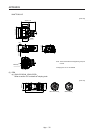
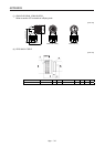
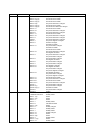
Oil seal
Motor plate/Caution plate
φ63
227
163
4
5
°
φ
2
6
5
φ
3
3
0
4 in total
Bottom
Bottom
Top
Bottom
Top
A
BC
D
Cooling fan connector viewed from the connection side
Motor flange direction
BC37772A
Top
Note 1. When the motor is used without the eyebolt, plug the threaded hole with a bolt of M12 × 20 or less.
2.
A
n angle adjusting washer is inserted into the eyebolt.