


4. CONNECTION OF SERVO AMPLIFIER AND SERVO MOTOR
4 - 4
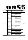
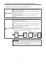
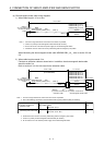
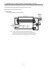
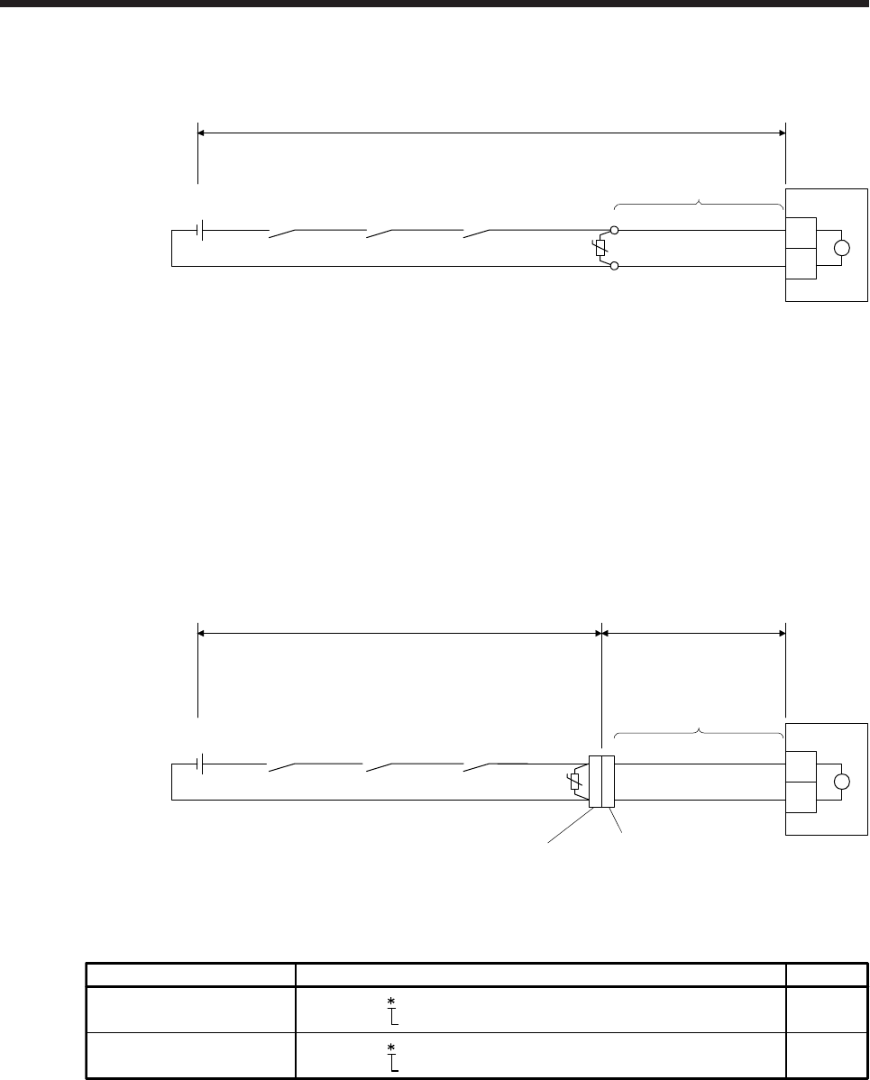
(b) Electromagnetic brake cable wiring diagrams
1) When cable length is 10 m or less
(Note 2)
(Note 3)
24 V DC power supply
for electromagnetic
brake
MBR
(Electromagnetic
brake interlock)
AWG20
AWG20
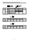
MR-BKS1CBL_M-A1-L
MR-BKS1CBL_M-A2-L
MR-BKS1CBL_M-A1-H
MR-BKS1CBL_M-A2-H
(Note 1)
B1
B2
ALM
(Malfunction)
Servo motor
10 m or less
(Note 4)
U
B
Note 1. Connect a surge absorber as close to the servo motor as possible.
2. There is no polarity in electromagnetic brake terminals (B1 and B2).
3. Do not use the 24 V DC interface power supply for the electromagnetic brake.
4. Create the circuit in order to shut off by interlocking with the emergency stop switch.
When fabricating the electromagnetic brake cable MR-BKS1CBL-_M-_, refer to section 5.5 and
5.6.
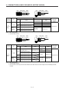
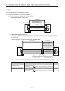
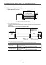
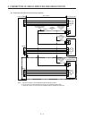
2) When cable length exceeds 10 m
Fabricate an extension cable as shown below. In addition, the electromagnetic brake cable
should be within 2 m.
Refer to section 4.3 for the wire used for the extension cable.
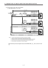
(Note 2)
b) Junction connector for
electromagnetic brake cable
(Note 2)
a) Junction connector for
extension cable
(Note 4)
(Note 5)
24 V DC power supply
for electromagnetic
brake
MBR
(Electromagnetic
brake interlock)
(Note 1)
ALM
(Malfunction)
Servo motor
(Note 3)
AWG20
B1
B2
B
AWG20
2 m or less
Extension cable
(To be fabricated)
U
50 m or less
MR-BKS1CBL2M-A1-L
MR-BKS1CBL2M-A2-L
MR-BKS1CBL2M-A1-H
MR-BKS1CBL2M-A2-H
MR-BKS2CBL03M-A1-L
MR-BKS2CBL03M-A2-L
Note 1. Connect a surge absorber as close to the servo motor as possible.
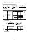
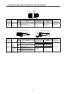
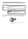
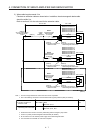
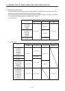
2. Use of the following connectors is recommended when ingress protection (IP65) is necessary.
CM10-CR2P- (DDK)
Junction connector Description IP rating
IP65
IP65
CMV1-SP2S- (DDK)
a)
b)
Wire size: S, M, L
Wire size: S, M1, M2, L
Junction connector for
electromagnetic brake cable
Junction connector for
extension cable
3. Create the circuit in order to shut off by interlocking with the emergency stop switch.
4. There is no polarity in electromagnetic brake terminals (B1 and B2).
5. Do not use the 24 V DC interface power supply for the electromagnetic brake.