


5. WIRING OPTION
5 - 23
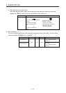
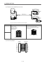
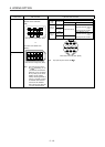
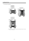
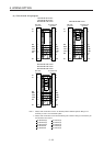
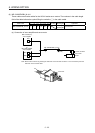
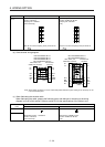
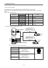
(b) Cable internal wiring diagram
MR-ENECBL2M-H-MTH
MR-ENECBL5M-H-MTH
MR-ENECBL10M-H-MTH
MR-ENECBL20M-H-MTH
(Note 2)
(Note 1)
P5
LG
1
2
MR
MRR
3
4
THM1 5
THM2 6
F
S
CN2-side
connector
Encoder-side
connector
9
SD
Plate
C
D
K
R
N
LG
MR
MRR
THM1
L THM2
SHD
P5
BAT BAT
GLG
P5
LG
1
2
MR
MRR
3
4
F
S
CN2-side
connector
Encoder-side
connector
9
SD
Plate
C
D
R
N
LG
MR
MRR
T
HM1 5
K THM1
T
HM2 6 L THM2
SHD
P5
BAT
BAT
GLG
(Note 2)
(Note 1)
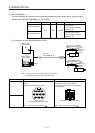
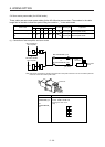
MR-ENECBL30M-H-MTH
MR-ENECBL40M-H-MTH
MR-ENECBL50M-H-MTH
P5
LG
1
2
MR
MRR
3
4
THM2 6 L
F
S
K
CN2-side
connector
Encoder-side
connector
THM1 5
9
SD
Plate
C
D
R
N
LG
MR
MRR
THM2
THM1
SHD
P5
G
LG
BAT
BAT
(Note 2)
(Note 1)
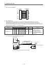
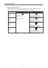
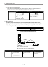
Note 1.
A
lways make connection for use in an absolute position detection system. Wiring is not
necessary for use in an incremental system.
2.
A
lways make connection for use with the following servo motors. Wiring is not necessary for
use with other servo motors.
HG-JR22K1M(4)
HG-JR30K1M(4)
HG-JR37K1M(4)
HG-JR45K1M4
HG-JR55K1M4
HG-JR15K1(4)
HG-JR20K1(4)
HG-JR25K1(4)
HG-JR30K1(4)
HG-JR37K1(4)