


5. WIRING OPTION
5 - 30
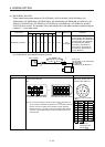
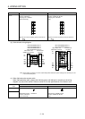
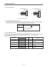
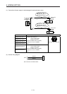
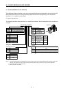
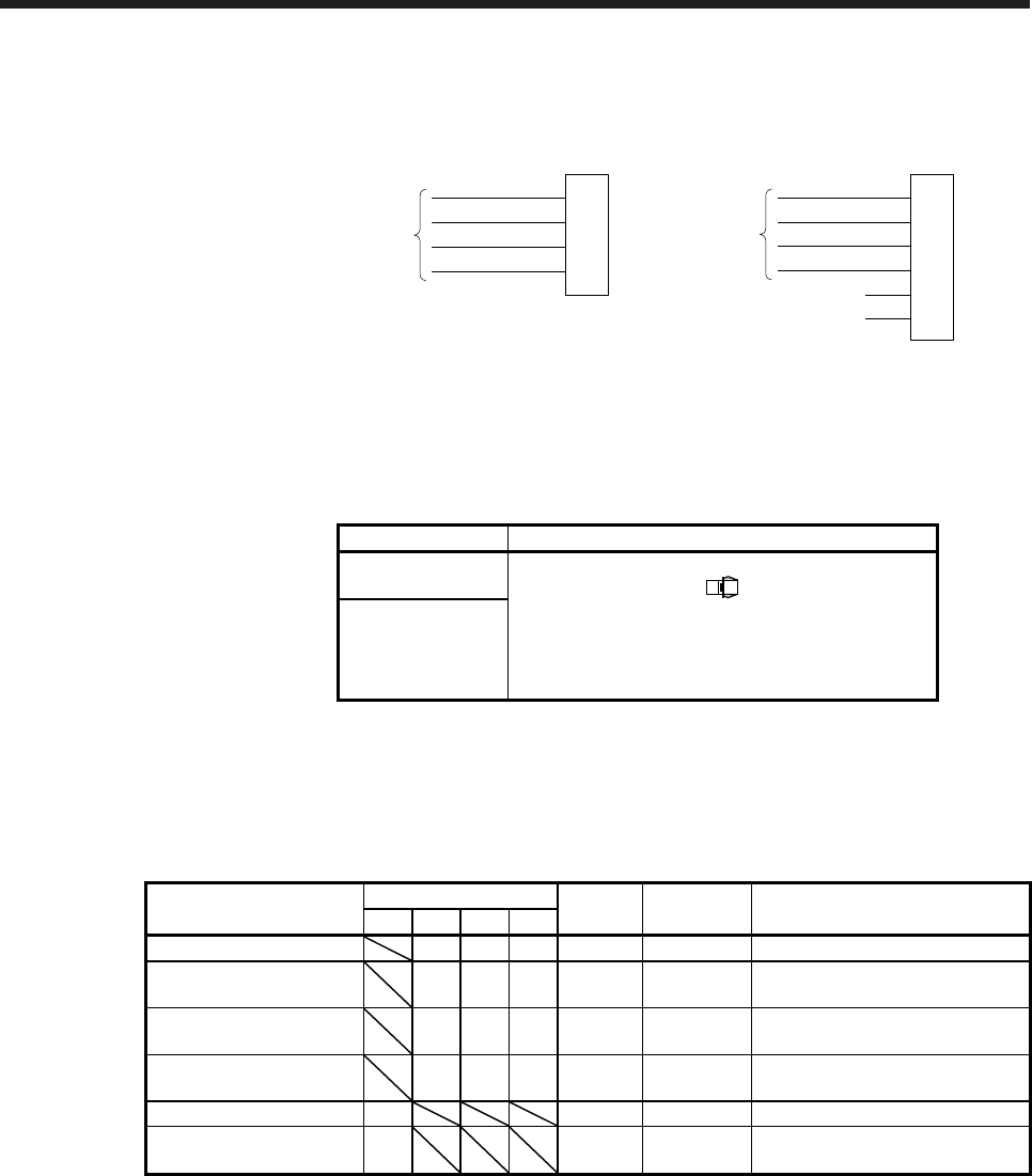
(2) Internal wiring diagram
1B
Servo motor power-
side connector
1A
MR-J4W03PWCBL_M-H
E
V
2B
W
2A
U
Yellow/green
White
Black
Red
(Note)
1B
Servo motor power-
side connector
1A
MR-J4W03PWBRCBL_M-H
E
V
2B
W
2A
U
3B B1
3A B2
Yellow/green
White
Black
Red
(Note)
Note. These are not shielded cables.
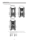
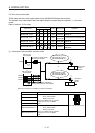
(3) When fabricating the motor power cable
When fabricating the cable, prepare the following parts, and fabricate it according to the wiring diagram
in (2) of this section. Refer to section 5.6 for the specifications of the cable to use.
Connector set model Servo motor-side connector
MR-J4W03CNP2-
2P
Tab housing: J21DPM-06V-KX
Contact: BJ2M-21GF-M1.0N
(JST)
MR-J4W03CNP2-
20P
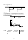
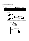
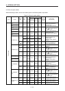
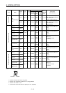
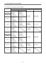
5.5 Electromagnetic brake cable
These cables are electromagnetic brake cables for the HG-MR/HG-KR series servo motors. The numbers in
the cable length field of the table indicate the symbol filling the underline "_" in the cable model.
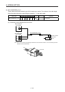
Refer to section 4.2.1 for wiring.
Cable model
Cable length
IP rating Bending life Application
0.3 m 2 m 5 m 10 m
MR-BKS1CBL_M-A1-L 2 5 10 IP65 Standard Load-side lead for HG-MR/HG-KR
MR-BKS1CBL_M-A2-L 2 5 10 IP65 Standard
Opposite to load-side lead for HG-
MR/HG-KR
MR-BKS1CBL_M-A1-H 2 5 10 IP65
Long
bending life
Load-side lead for HG-MR/HG-KR
MR-BKS1CBL_M-A2-H 2 5 10 IP65
Long
bending life
Opposite to load-side lead for HG-
MR/HG-KR
MR-BKS2CBL03M-A1-L 03 IP55 Standard Load-side lead for HG-MR/HG-KR
MR-BKS2CBL03M-A2-L 03 IP55 Standard
Opposite to load-side lead for HG-
MR/HG-KR