


6. HG-MR SERIES/HG-KR SERIES
6 - 1
6. HG-MR SERIES/HG-KR SERIES
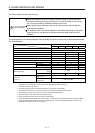
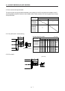
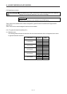
This chapter provides information on the servo motor specifications and characteristics. When using the HG-
MR/HG-KR series servo motor, always read the Safety Instructions in the beginning of this manual and
chapters 1 to 5, in addition to this chapter.
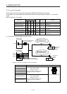
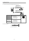
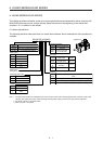
6.1 Model code definition
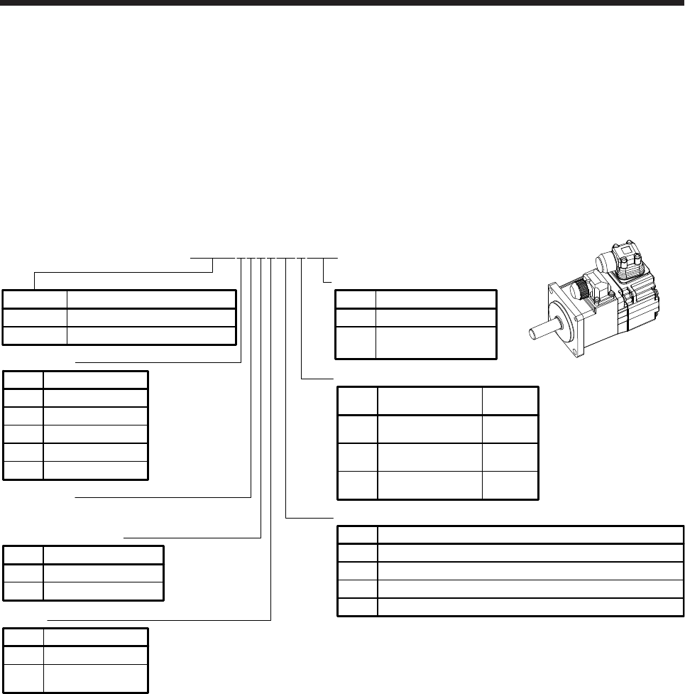
The following describes what each block of a model name indicates. Not all combinations of the symbols are
available.
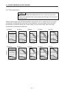
Low inertia/Small capacity
Appearance
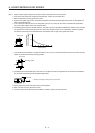
Shaft type
Symbol Shaft shape
None
Standard
(straight shaft)
(Note 1)
K
(Note 1)
D
Keyway shaft
(with key)
D cut shaft
053 to 73
HG-MR_
HG-KR_
23 to 73
053/13
Rated speed
3000 [r/min]
None None
Electromagnetic brake
Symbol Electromagnetic brake
B
With
None None
Oil seal
Symbol Oil seal
(Note 2)
J
With
05 0.05
Rated output
Symbol
Rated output [kW]
1 0.1
2 0.2
4 0.4
7 0.75
None
Reducer
Symbol
G1
For general industrial machine (flange-mounting)
Flange-mounting flange output type for high precision application
Flange-mounting shaft output type for high precision application
Reducer
None
G5
G7
HG-MR Ultra-Low inertia/Small capacity
Series
Feature
HG-KR
H
G
-KR13
B
JG1
D
W0
C
None Standard
Special specification
Symbol Special specification
(Note 3)
W0C
Servo motor with
functional safety
Note 1. The special shaft applies to the standard servo motor and servo motor with an electromagnetic brake. However, the key shaft
(with key) also applies to the servo motor with flange-mounting shaft output type reducer for high precision application.
2. For details, contact your local sales office.
3. Refer to section 1.5 for details.