


SECTION FOUR: Installing and wiring the 2701
958 Installation Manual, Rev. A1 Page 19
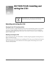
Installing the AN205-P antenna
Choosing the best antenna mounting location
The 2701 operates with Northstar’s AN205-P “combo” GPS/DGPS antenna. For mounting
recommendations, see see “Choosing the best mounting location” beginning on page 12.
If position data is intermittent, make sure you have the proper cable length, and check the quality of
the antenna location and the quality and proper termination of the connectors. Also, make sure that
the 2701’s ground lug terminal is securely connected with a heavy gauge conductor to ship’s ground.
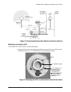
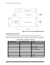
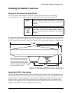
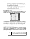
Figure 13: Northstar AN205-P antenna dimensions
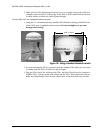
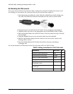
Connecting the 2701 to the antenna
The 50-foot antenna cable connects the 2701 with the AN205-P antenna. The cable length must be a
maximum of 50 feet, but can be shortened to the desired length. Don’t make any tight bends in the
cable, and fasten it along its length to avoid chafing or whipping or any kind. Coil up any unused
length of cable. Be sure that the cable connectors are securely fastened. NOTE: Installations that
require a cable length from 50 to 100 feet should order the AN206 combo antenna and a 100-foot
length of coaxial cable from the Northstar Sales Department.
NOTE:
Before permanently installing the AN205-P, try temporarily
installing it and using the 958 to see if the antenna location
works well.
CAUTION!
Don’t mount the antenna near rotating warning beacons or
strobe lights, electric motors, fluorescent lights, or other RF
sources. These can create RF interference to the differential
reception.
7. 00
2.5
3. 5
TNC
Use the locking nut shown to prevent
rotation of the antenna or bottoming
out of the mounting stanchion into the
threaded mount portion of the antenna.
If done with enough force, either of
these may break the antenna.