


ENTER - The current total can be manually stored in
the monitor's flash memory. Press and hold the
ENTER key for 2 seconds. The display will respond
with a flashing TOTALSVD and then will return to RUN
mode.
RESET TOTAL - To reset the monitor total display,
press the MENU and ENTER keys simultaneously
until TOTALRST starts to flash. The TOTALRST will
stop flashing and the display will return to RUN mode
at the conclusion of the reset procedure.
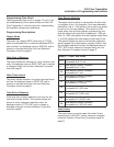
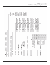
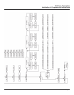
Programming Operation (PROGRAM) Mode
The programming mode allows the user to change the
configuration and adjust the calibration of the meter.
The FLR Flow Transmitter has two types of configura-
tion changes in program mode:
• To view or change selections from a
predefined list
• To view or change numeric entries
During programming operation, the following four but-
ton functions are provided:
MENU - Enters and exits programming mode.
Change to programming mode by pressing the MENU
key once. The mode indicator on the display will
change from RUN to PROGRAM.
UP ARROW - Use the UP ARROW key to scroll
through the configuration choices in a bottom-to-top
order. For numeric setup, this button increments
numeric values.
RIGHT ARROW - Use the RIGHT ARROW key to
scroll through the configuration choices in a top-to-bot-
tom order. For numeric setup, this button moves the
active digit to the right.
ENTER - Used to enter menus to change configura-
tions and to save programming information.
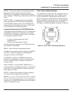
NOTE: If any input value exceeds the meter's capabili-
ties the LIMIT indicator will begin to flash indicating an
invalid entry. Press ENTER once to return to the entry
screen to reenter the value.
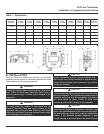
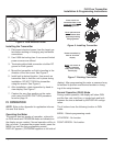
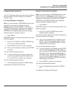
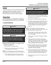
Cover Removal/Reinstallation
It is necessary to remove the FLR Transmitter cover to
access the programming keys. Use a Phillips screw-
driver to remove the 4 screws that hold the cover in
place, turning them counterclockwise. When program-
ming is completed, reinstall the cover. To properly seat
the built-in cover gasket, tighten the cover screws
clockwise in a criss-cross pattern as shown in Figure 8.
Figure 8. Cover Screw Tightening Sequence
FLR Flow Transmitter
Installation & Programming Instructions
Page 7
®