


Output Mode
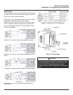
The FLR Flow Transmitter offers three analog output
modes:
• 4–20 mAOutput Signal
• 0–5 Volts DC Output Signal
• 0–10 Volts DC Output Signal
The output mode selected is determined by the type of
peripheral device being connected to the FLR Flow
Transmitter.
The displayed name is OUT MODE and is viewed or
changed using the List Item Selection Procedure
found on page 8.
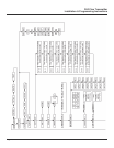
Note: Setup prompts and descriptors for configuring
and calibrating the analog output will correspond to
the output mode selected. Refer to the Flow Chart on
pages 10 and 11.
Flow at 0V or 4mA Setting
This selection is used to configure the minimum ana-
log output signal to the corresponding flow rate. Enter
the flow rate at which the minimum analog output sig-
nal is required using the Numeric Value Entry
Procedure found on page 8.
Flow at 5V, 10V or 20mA Setting
This selection is used to configure the maximum ana-
log output signal to the corresponding flow rate. Enter
the flow rate at which the maximum analog output sig-
nal is required using the Numeric Value Entry
Procedure found on page 8.
Calibration of Analog Output
This selection allows access to the calibration and
testing of the analog output signal. Calibration of the
Analog Output is preset at the factory, but can be
changed to customize calibration for your installation.
To test or change the analog output calibration, it is
first necessary to change the default setting for CAL
OUT? from NO to YES.
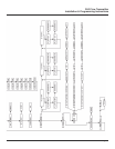
Note: Setup prompts and descriptors for configuring
and calibrating the analog output will correspond to
the output mode selected. Refer to the Flow Chart on
pages 10 and 11.
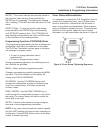
1. At the CAL OUT? prompt press ENTER.
NO will display
.
2. To change to YES, press either arrow key.
3. The analog output will go to its minimum output
level. A numeric value between 0–4000 will dis-
play. This is an internal number used to drive
the analog output.
4. To increase the analog output signal level, press
the UP ARROW key. To decrease the analog
output signal level, press the RIGHT ARROW
key.
5. Press ENTER to store the setting.
6. The analog output will go to its maximum output
level. A numeric value between 0–4000 will dis-
play. This is an internal number used to drive
the analog output.
7. To increase the analog output signal level, press
the UP ARROW key. To decrease the analog
output signal level, press the RIGHT ARROW
key.
8. Press ENTER to store the setting.
9. The unit will advance to the analog output test
mode. The analog output will go to its minimum
output level. A numeric value of 0 will display.
For test purposes, the analog output signal can
be run up or down in increments of 1 milliamp or
1 volt, depending on the OUT MODE selected.
10. To increase the analog output signal level, press
the UP ARROW key. To decrease the analog
output signal level, press the RIGHT ARROW
key.
11. Press ENTER to exit the analog calibration
mode.
12. The unit automatically advances to the PASS-
WORD feature.
FLR Flow Transmitter
Installation & Programming Instructions
Page 13