


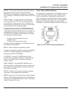
Password
Password protection prevents unauthorized users from
changing programming information. Initially the pass-
word is set to all zeros. Its displayed name is
PASSWORD and is viewed or changed using the
Numeric Value Entry Procedure found on page 8.
Restore Defaults
This feature allows you to restore factory calibration
data. Its displayed name is RES DFLT. To restore fac-
tory calibration data, select YES, then press ENTER.
V. MAINTENANCE
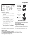
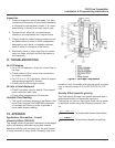
Cartridge Cleaning (Figure 4 on page 5 and
Figure 9 on page 15)
1. Disconnect the transmitter cable.
2. Remove the transmitter from the line. Remove
excess piping from transmitter.
NOTE: It is not necessary to remove the aluminum
housing from the transmitter to remove it from the line.
3. Thoroughly wipe off the entire transmitter sur-
face using mild detergent or isopropyl alcohol.
4. Remove the inlet port cap, wave spring, retain-
ing ring, and cone assembly from the transmitter
body (Figure 9 on page 15).
5. Gently push the body towards the outlet port.
6. The piston, inner magnet and transmitter spring
are secured within the transmitter body with a
retaining ring. Remove the retaining ring with a
small screwdriver, then the internal components
can be removed from the body (Figure 9 on
page 15).
NOTE: If internal parts do not slide freely from
cartridge, use a wooden dowel inserted into the outlet
port of the transmitter to push parts out.
7. Place all parts on a clean work surface. Clean
and inspect all parts. Replace any that appear
worn or damaged.
Check inlet port O-ring for damage and replace
if required.
8. Reassemble the transmitter by inserting the
transmitter spring into the body, followed by the
piston/inner magnet assembly. A slight compres-
sion of the piston against the spring is required
during installation of the retaining ring.
9. Gently push body assembly into the outlet end
of the transmitter enclosure. The flat surface of
the body outlet port should be flush with the
transmitter enclosure opening.
10. With the transmitter positioned vertically on a
flat surface, inlet port facing up, install the trans-
mitter cone assembly and wave spring into the
body and secure with the inlet port end cap.
11. Reinstall transmitter to the line. Reconnect elec-
trical power.
FLR Flow Transmitter
Installation & Programming Instructions
Page 14
Before attempting to remove the transmitter from the
line, check the system to confirm that line pressure
has been reduced to zero PSI. Failure to follow
these instructions could result in serious personal
injury or death and/or damage to the equipment.
WARNING
Always disconnect the primary power source before
opening the enclosure for inspection or service.
Failure to follow these instructions could result in
serious personal injury or death and/or damage to
the equipment.
WARNING
Do not use aromatic hydrocarbons, halogenated
hydrocarbons, ketones, or ester based fluids on
polycarbonate lens. Failure to follow these
instructions could result in damage to the transmitter.
WARNING