


Installation Recommendations
The transmitter is a simple device to install. However,
the following measures are recommended for reliable,
trouble-free operation:
DO - Align pipe accurately. Piping should be accurate-
ly aligned and of correct length. The high pressure
body of the transmitter can withstand shock and
flow/pressure pulsation. However, the piping should be
firmly supported by external mounting brackets, both
upstream and downstream of the meter, to avoid any
pipe flexing action that could reduce meter life.
DO - Use rigid mounting. If the transmitter inlet or out-
let are to be rigidly mounted, and the opposing port is
to be connected to flexible hose, the end connected
with the flexible hose must be rigidly mounted.
DO - Use Teflon
®
tape for sealing NPT fittings.
DO - Install unions. Install a union near the inlet or
outlet of the transmitter. This will facilitate quick, easy
removal and inspection during periodic maintenance
procedures.
DO - Ensure the fluid is traveling in the direction of the
flow arrow (Figure 5 on page 6).
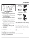
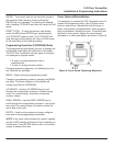
NOTE: The FLR Flow Transmitter display board can be
rotated 180
°
for optimal viewing. Simply remove the
FLR Flow Transmitter cover, disconnect the ribbon
cable, rotate the display board 180
°
, reconnect the rib-
bon cable, and reinstall cover. See Figure 8 on page 7
for cover screw tightening sequence.
DO - Use at least a 200 mesh (74 micron) filter. The
transmitter will allow particulate to pass that would jam
most valves and flow controls. Systems that do not
have filtration should be equipped with at least a 200
mesh (74 micron) filter. Most hydraulic systems
already have much finer filtration. Dirt, ferrous metal or
sealing agents, such as Teflon tape may lodge and
cause malfunction. If the transmitter is jammed at a
fixed position, follow cleaning and maintenance
instructions. See Maintenance section on page 14.
DON’T - Use thread locking compounds as thread
sealant.
DON’T - Install the transmitter near turbulence pro-
ducing fittings such as elbows, reducers, close cou-
pled valves, etc. The transmitter does not require flow
straighteners or special lengths of straight inlet/outlet
piping to stabilize turbulent flow patterns. However, to
assure maximum operational reliability, avoid installa-
tion of elbows, valves and/or reducers immediately
adjacent to the transmitter inlet.
DON’T - Install the transmitter near fast-acting valves.
Fast-acting valves have the potential to create high
magnitude hydraulic pressure spikes. These spikes
can damage the internal components of the transmit-
ter, resulting in inaccuracies or malfunction.
DON’T - Allow unidirectional transmitters to be
operated against the direction of the flow arrow. The
standard transmitter is a unidirectional flow transmitter.
The piston acts as a check valve to block flow in the
reverse direction. This causes an excessive pressure
differential, which can result in damage to internal
transmitter components. The transmitter is also avail-
able in a modified design, which offers a reverse flow
bypass feature to accommodate bi-directional flow.
NOTE: Transmitters with a reverse flow bypass
feature are available. Consult factory for details.
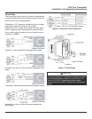
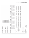
Electrical Connections
Cable may be shortened or lengthened as required by
installation. The cable is soldered directly to the
electrical connector at the factory.
Cable replacement requires disassembly of the
electrical connector.
FLR Flow Transmitter
Installation & Programming Instructions
Page 4