


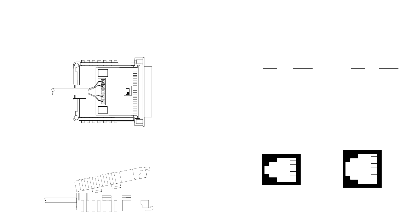
9. Insert the strain relief assembly with the wire going through it
into the slot in the bottom half of the modem case and set it into the
recess in the case.
10. BEND the top half of the case as necessary to place it over the
strain relief assembly. Do not snap the case together yet.
11. Insert one captive screw through a saddle washer and then
insert the captive screw with the washer on it, through the hole in the
DB-25 end of the case. Snap that side of the case closed. Repeat the
process for the other side. This completes the cable installation
process.
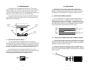
4.1.2 TWISTED PAIR CONNECTION USING MODULAR JACKS
The modular versions of the Model 2017P have an RJ-11 or RJ-45
jack mounted in the case. These jacks are prewired for a standard
TELCO wiring environment. To be sure you have the right wiring, use
the table below as a guide.
RJ-1
1 SIGNAL RJ-45 SIGNAL
1----------------GND
†
1 --------------N/C
2----------------RCV- 2 --------------GND
3----------------XMT+ 3 --------------RCV-
4----------------XMT- 4 --------------XMT+
5----------------RCV+ 5 --------------XMT-
6----------------GND 6 --------------RCV+
7 --------------GND
8 --------------N/C
†
Connection to ground is optional
AT&T standard modular color codes
4.2 COMPLETING THE INSTALLATION
Once you have configured the unit for DTE or DCE and connected
the twisted pair wires correctly, simply plug the Model 2017P into the
RS-232 data port. Remember to insert and tighten the two captive
connector screws.
The Model 2017P requires no power supply or batteries for
operation. It will work automatically at any data rate from 50 to 19,200
bps, as long as there is any data or control voltage being applied.
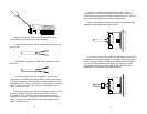
7 8
1 - Blue
2 - Yellow
3 - Green
4 - Red
5 - Black
6 - White
1 - Blue
2 - Orange
3 - Black
4 - Red
5 - Green
6 - Yellow
7 - Brown
8 - Slate
RCV G XMT
RCV G XMT
- + - +