


37
38
APPENDIX D
(continued)
PATTON MODEL 2094
INTERFACE PIN ASSIGNMENTS
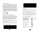
M/34 Connector, Terminal Interface
Pin # Signal
A GND (Earth Ground/Shield)
B SGND (Signal Ground)
D CTS (DCE Source)
E DSR (DCE Source, Always On)
F CD (DCE Source)
L LL (Local Loop, DTE Source)
M TM (Test Mode Indicator (DCE Source)
N RL (Remote Loop, DTE Source)
P TD (Transmit Data +, DTE Source)
R RD (Receive Data +, DCE Source)
S TD/ (Transmit Data -, DTE Source)
T RD/ (Receive Data -, DCE Source)
U SCTE (Transmit Clock+, DTE Source)
V RC (Receiver Clock +, DCE Source)
W SCTE/ (Transmit Clock-, DTE Source)
X RC/ (Receiver Clock -, DCE Source)
Y TC (Transmitter Clock +, DCE Source)
AA TC/ (Transmitter Clock -, DCE Source)
KK Aux. Power Input (+5VDC @ 300mA)
APPENDIX E
PATTON MODEL 2094
POWER SUPPLY INTERFACE
Via Main 5VDC power jack (J1)
Center Pin: 5VDC @ 300 mA
Outer Barrel: Ground
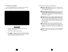
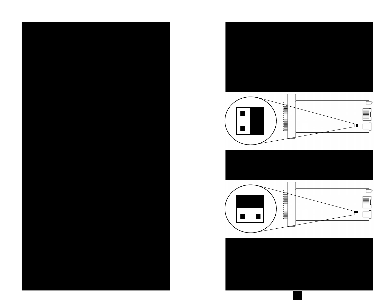
Jumper Position for Power via DC Power Jack (default):
Via Auxiliary Power Supplied to Pin KK on V.35 connector
DC Power supplied to pin KK must be 5VDC ± 5%, 300mA minimum.
Jumper Position for Power via Pin KK:
NOTE: Model 2094 is factory configured to accept power from
the enclosed DC wall adapter (See Sections 4.3.1 and 4.3.2
above). If you wish to supply power via pin KK on the interface,
you must change the setting of the
power supply jumper
on the
printed circuit board. All power sources must be SELV (Circuit,
Safety Extra Low Voltage) specified. (See CENELEC EN60950,
Section 1.2.8.5)