


Installation
Needed for Installation (not included)
Mounting hardware for the inverter
Tools
Mounting
Step #1: The STP-150 should be mounted on a solid flat surface capable of
handling the weight of the unit, with space around the unit for ventilation. It
is very important that the unit be secured using the proper sized mounting
hardware (not included) to keep the unit from moving around or becoming
loose in emergency situations.
CAUTION: The power inverter must be mounted securely in any
type of moving vehicle. In an emergency situation, if the power
inverter is not securely mounted, it could cause bodily injury
Connection to Power Source
The STP-150 requires connection to a standard 12 volt DC power source as
found in most cars, trucks, RVs and boats. The power source must provide
between 11 and 15 volts DC. The power source must be able to provide
sufficient current to power the load. At full power, the STP-150 will draw
about 15 amps. The STP-150 comes with a cigarette lighter plug for easy
connection to the power source. The tip of the plug is positive and the side
contacts are negative. Insert the plug into a cigarette socket by pushing
firmly for a good connection. A red indicator light on the adapter will light up.
Do not use a 12V extension cord with this unit.
Testing the Power Inverter
Make sure the 12 volt power source is wired properly to the power
inverter. With nothing plugged into the 115 VAC outlets, turn on the power
switch of the STP-150.
If the green power light does not come on, turn the power switch off and
check your wiring and external fuse.
With the inverter turned off, plug the appliance you want to use into the
115 VAC power outlet on the unit. Turn on the power switch of the STP-
150. The appliance should now be operational.
Operation
Equipment Power Usage
It is important to use only products that draw less than 150 watts with the
STP-150. Use of products greater than 150 watts may either cause the
protection circuitry of the STP-150 to shut down or the fuse to blow.
Repeated use of excessive power draw can cause failure of the STP-150.
How to calculate power usage.
Most products have a power rating on them such as 45 watts. Others may
be marked with their current draw, such as .9 amps. To convert the current
to watts multiply the current by 115. Thus .9 amps x 115 = 104 watts.
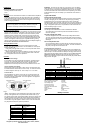
Turn the unit on
Plug the appliance you want to use into the 115 VAC power outlet on the
STP-150 (see Fig. 1 below). Turn on the power switch of the STP-150 so
the green power light is illuminated. Turn on the appliance. The appliance
should now be operational.*
Fig. 1
* Note : Some products, such as televisions, draw a high surge current to
start up. If the appliance does not operate and the inverter turns off, you
may need a larger inverter. Check that the battery and the 12V wiring to the
inverter is large enough to handle the current draw. Be sure the battery is
fully charged. You may need to turn the power switch the STP-150 on and
off a few times to get the appliance “started”. Some motors and televisions
may require this technique to get them operational.
Typical Power Usage Chart
Typical Appliance Typical Appliance
Current Draw
Cellular phone charger 20 watts
Camcorder 30 watts
VCR 45 watts
Soldering iron 45 watts
Laptop computer 70 watts
13” TV 70 watts
100 watt work light 100 watts
Small stereo system 120 watts
Important: The STP-150 will not operate most appliances
designed to produce heat such as hair dryers, heaters, toasters,
and coffee makers.
Important: The STP-150 can draw up to 15 amps from your car’s battery
when operating. If you are using it for extended periods of time, you will want
to operate your car occasionally to maintain the charge in your car’s battery.
The STP-150 will also draw a small current when not operating, so it should
be disconnected from your car’s battery if your vehicle will not be used for a
few days.
Lights and Alarms
Power Indicator (Green light)
The green light is illuminated when the inverter is turned on and is operating
normally. If this light goes out, either the 12 volt power supply is missing
(possible blown fuse) or some fault condition has occurred. These fault
conditions include: output overload, output short circuit, low input voltage and
over-temperature of the unit. This can happen if a device has a large start-up
surge, if an appliance (like a drill or saw) is stalled or if the inverter does not
have a circulating supply of cool air.
Overload Fault (Red light)
The red light is illuminated when a current overload fault is detected.
An overload fault occurs when the power draw exceeds the inverter’s
maximum capability.
An under-voltage fault (beep)
An under-voltage fault can occur when the input voltage reaches about
10.2 volts. The STP-150 will sound a continuous alarm and shut off when
the input voltage drops to 9.6v to protect your battery from being completely
discharged.
An over-temperature fault
An over-temperature fault occurs when the STP-150 internal circuitry gets
too hot due to overload or improper air circulation. The STP-150 will turn off
the green power light and the unit will turn off.
Fuse Replacement (see figure 2)
If you overload the STP-150, it is possible that the fuse in the cigarette plug
might blow. If this happens, unplug the cigarette plug from the power source,
wait for the tip to cool and unscrew the metal tip on the plug. Remove the tip.
Remove the fuse and install a new fuse rated at 15 amps. Never use a fuse
greater than 15 amps. Replace the tip and screw firmly but do not over
tighten. Always determine why the fuse blew and remedy the problem before
using the STP-150 again.
Fig. 2
Troubleshooting Guide
Problem Possible cause Solution
• Unit does not • In
p
ut volta
g
e is •
A
ttach to
p
ro
p
er
p
ower
• Unit o
p
erates • Load is tr
y
in
g
to • Be sure the load is less than
• Unit o
p
erates • Inverter is in •
A
llow inverter to cool down.
• Low batter
y
• In
p
ut volta
g
e is • Make sure car en
g
ine is
• Television and • RF interference • Position the
p
ower inverter
• 115 VAC • Modified sine wave • Use a true RMS meter like a
Product Specifications
Max. continuous power output 150 watts
Surge (peak) power output 300 watts
Input voltage range 11 to 15 vdc
No load current draw < 0.2 amp
Full load current draw 15 amps DC
Low battery alarm/shut-down 10.2 V, +/- 0.5 V
Efficiency 90%
Output waveform Modified sine wave
Weight 1.2 lbs.
Size 5.7” x 4.3” x 2”
Battery Life Chart