


Radar Installation Manual Page 13
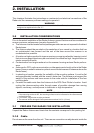
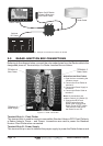
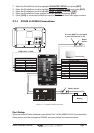
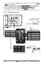
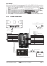
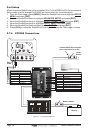
12-24VDC
JUNCTION BOX
EXTERNAL SWITCH
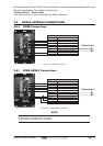
Green
Blue
Black
White
Black
Orange
Red
Brown
Yellow
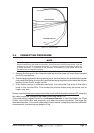
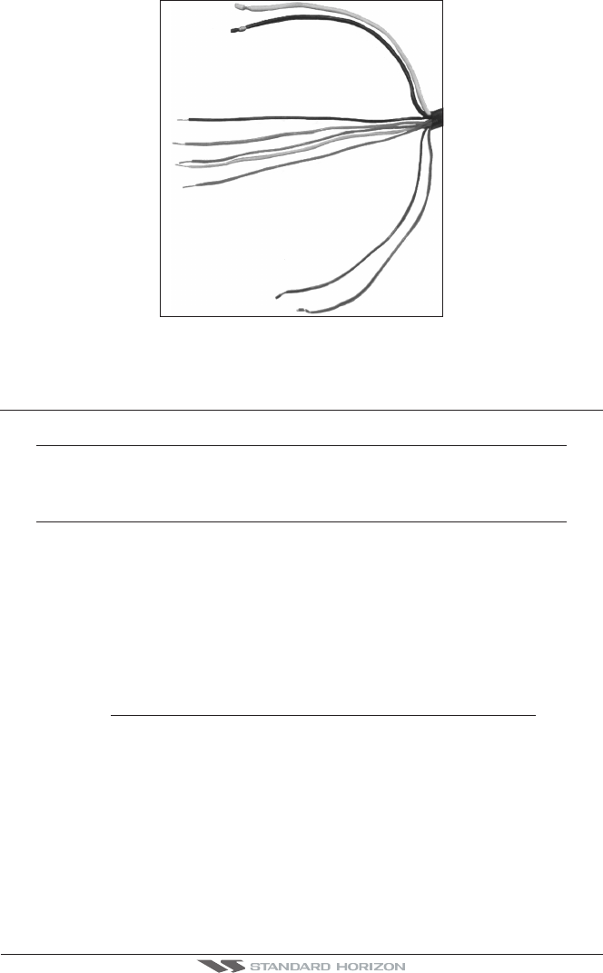
Figure 2.3 - Antenna Cable
2.4 CONNECTION PROCEDURE
NOTE
In the following procedure the small wires must be stripped and tinned, and then connected to the
proper connections in the Radar Junction Box, and to pins on the On/Off control switch. If you are
uncertain of your skill in completing these tasks, it is strongly advised to obtain the services of a
qualified technician. It is essential to the operation and reliability of your Radar that these
procedures are accomplished properly.
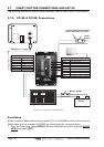
1. Arrange the free end of the Antenna cable so that the wires will reach their intended
points for connections.
2. The two large wires must reach a power panel; the five leads in the braided fabric jacket
must reach the Radar Junction Box and the two remaining leads must reach the desired
location for the On/Off control switch.
3. If the leads must go in different directions, first route the five leads in the fabric
braid to the Junction Box. Then extend the shorter leads using the same size or
larger size wire.
Please note that
the power supply level at the Junction Box should be at least 12V since due
the cable length the voltage at the Radar could drop below 10V.
The power supply cables should be of adequate diameter to feed the Radar, the Chart
Plotter, the Junction Box and eventually any other instrument connected. The larger the
diameter the better. A too small cable section could cause voltage drop over the cable with
consequential overheating and danger of fire.