


Page 11Phantom PS1000
2. Connect the red power wire to a 13.8 VDC ±20% power source. Connect
the black power wire to a negative ground.
3. If an optional remote extension speaker is to be used, refer to next section
for connections.
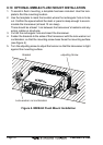
4. It is advisable to have a Certified Marine Technician check the power output
and the standing wave ratio of the antenna after installation.
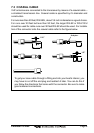
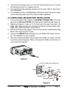
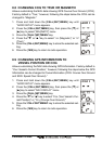
8.3 CMP25 RAM+ MICROPHONE INSTALLATION
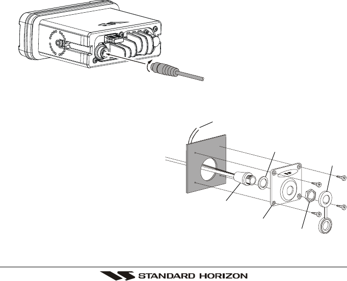
1. Connect the RAM+ MIC Cable to the RAM MIC CONNECTOR on the rear
panel of the Phantom PS1000, then tighten the Cable Nut (See Figure 2).
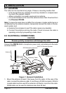
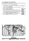
2. Referring to Figure 3, make a 1.2” (30 mm) hole in the wall, then insert the
RAM+ MIC Cable into this hole. Connect the Gasket and Mount Base to the
RAM+ MIC Cable Connector using the Nut.
3. Drill the four Screw holes (approx. 2 mm) on the wall, then install the Mounting
Base to the wall using four screws.
4. Connect the CMP25 RAM+ Microphone to the RAM+ MIC Cable Connec-
tor. The installation is now complete.
5. Wires for a external speaker are provided on the RAM+ mic cable. Connect
any 8 Ohm external speaker. When connected the RAM+ controls the vol-
ume level of this speaker.
Wall
Gasket
Mounting Bracket
RAM MIC Cable
Cap
Nut
EXP SP Cable for the RAM+ MIC
Figure 2
Figure 3