


WHITE-RODGERS
Printed in U.S.A.
PART NO. 37-5488A
Replaces 37-2935-1
37-9333-1
9512
TYPE 8B43A-601
RELAY-HOT WATER CONTROL
For Use With Line Voltage Primary Control
(Suitable for External Zone Valve Load)
INSTALLATION INSTRUCTIONS
Operator: Save these instructions for future use!
WHITE-RODGERS DIVISION
EMERSON ELECTRIC CO.
9797 REAVIS RD., ST. LOUIS, MO. 63123
(314) 577-1300, FAX (314) 577-1517
9999 HWY. 48, MARKHAM, ONT. L3P 3J3
(905) 475-4653, FAX (905) 475-4625
R
DESCRIPTION
FAILURE TO READ AND FOLLOW ALL INSTRUCTIONS CAREFULLY BEFORE
INSTALLING OR OPERATING THIS CONTROL COULD CAUSE PERSONAL
INJURY AND/OR PROPERTY DAMAGE.
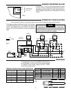
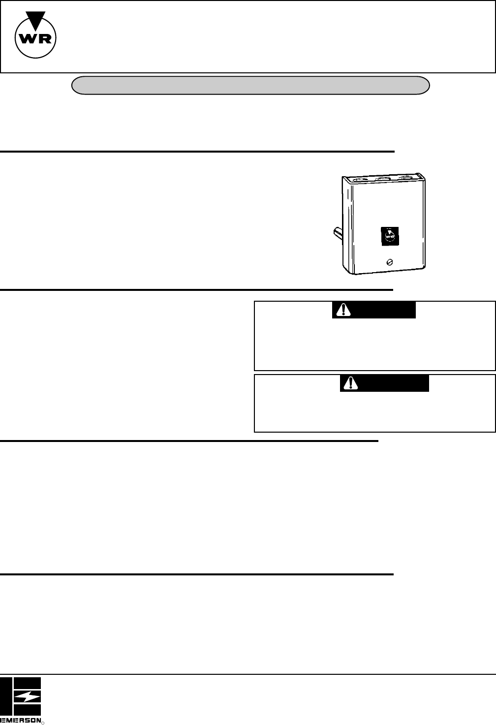
These Relay-Hot Water Controls combine into a single
enclosure: a high limit control, low limit-circulator control,
circulator relay, transformer, together with terminals for
wiring. They are for use on boilers equipped with tankless
domestic coil.
Although these controls are designed for use with a line
voltage gas valve or oil burner control, they may also be
used with low voltage primary controls.
The internal transformer supplies power for operating the
relay coil and systems zoned with motorized water valves.
ELECTRICAL DATA
Input Voltage: 120V.A.C., 60Hz
Circulator Motor: 120V.A.C. 8F.L.A. 48L.R.A.
Burner Circuit: 120V.A.C. 8F.L.A. 48L.R.A.
Ignition Trans.: 3.0 Amps
Burner Motor: 7F.L.A. 42L.R.A. or 125 VA Pilot Duty
Motorized Valve: 1.2A. Max.
Room Thermostat:
Set adjustable heat anticipator at 0.25 Amps. For fixed
anticipation thermostats, use 0.20 to 0.30 Amp. heater.
SPECIFICATIONS
To prevent electrical shock and/or equipment
damage, disconnect electric power to system, at
main fuse or circuit breaker box, until installation
is complete.
If in doubt about whether your wiring is millivolt, line, or
low voltage, have it inspected by a qualified heating and
air conditioning contractor, electrician, or someone famil-
iar with basic electricity and wiring.
Do not exceed the specification ratings.
All wiring must conform to local and national electrical
codes and ordinances.
This control is a precision instrument, and should be
handled carefully. Rough handling or distorting compo-
nents could cause the control to malfunction.
PRECAUTIONS
CAUTION
Do not use on circuits exceeding specified
voltages. Higher voltages will damage control
and could cause shock or fire hazard.
WARNING
If the boiler manufacturer recommends a control location,
then follow such recommendations. Otherwise, locate
the control as close to the top of the boiler as possible, but
not in the same section of the boiler that has fittings for
domestic hot water. Never locate the control near a return
pipe to the boiler.
THERMAL DATA
Range: High Limit - 140° to 240°F (60° to 116°C)
Low Limit / Circ. - 100° to 200°F (38° to 94°C)
Differential: High Limit - 10°F Fixed (5.5°C)
Low Limit / Circ. - 10° to 35°F Adj. (5.5° to 19°C)
Switch Action: High Limit - Open on rise
Low Limit / Circ. - SPDT
Well: 1/2" or 3/4" Thread Size
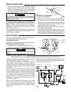
INSTALLATION
Install control as follows:
1. Install well securely into proper tapping.
2. Remove control cover. Then loosen the two screws
holding well clamp to back of case. NOTE: Loosen
until ends of screws are flush with well clamp for
easiest assembly.