2
Bosch Security Systems | 04-2003 | 3922 988 43318 en
Digital Congress Network | Installation and Operating Manual | Chapter 5 - Control using PC
en | 5-4
LBB 3511/00 PC Card for Multi-CCU Systems
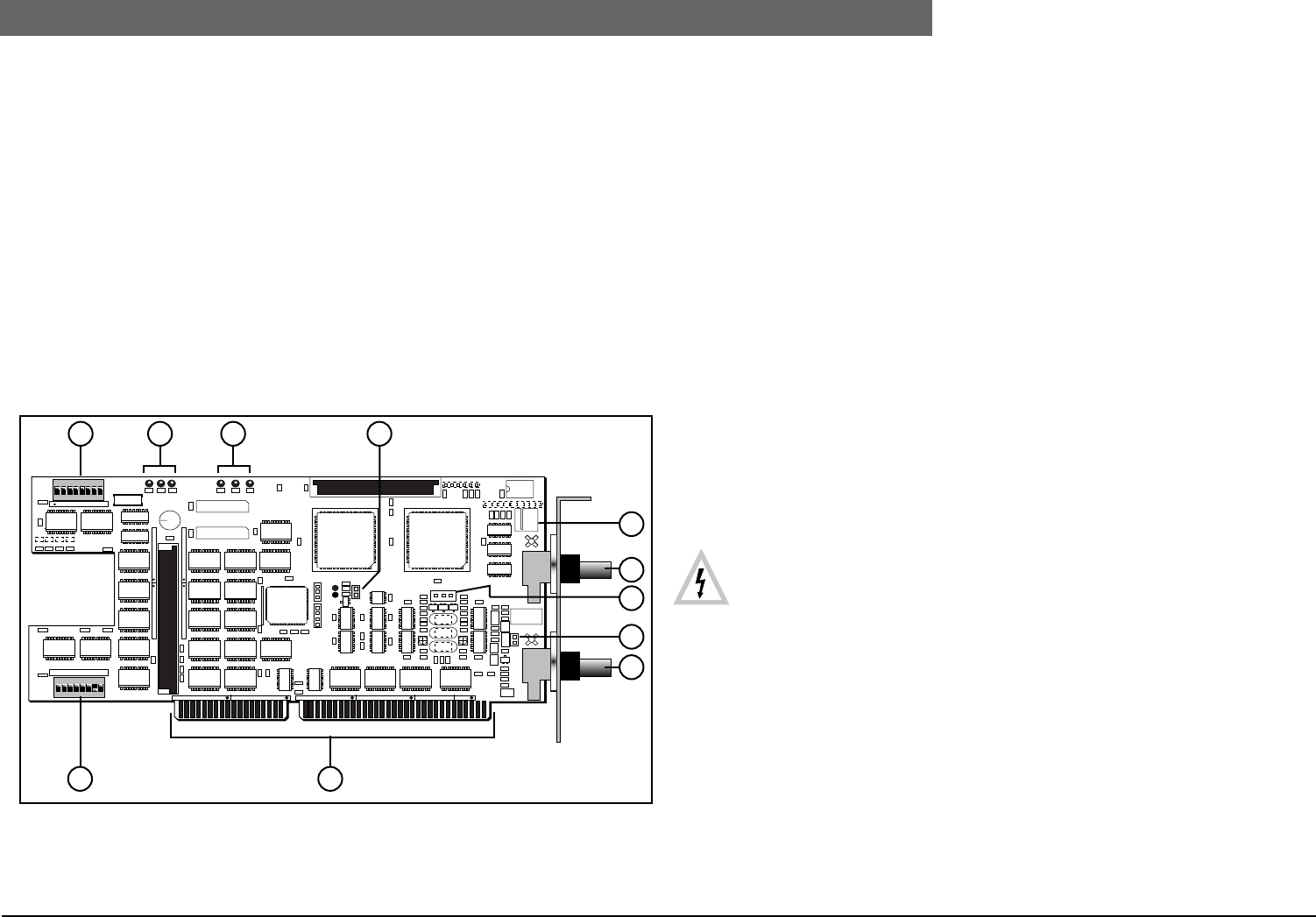
5.4 LBB 3511/00 PC Card for Multi-CCU Systems
The interface card LBB 3511/00 provides the interface between a master PC and interconnected
CCUs type LBB 3500/35 only. The card is installed in a 16-bit ISA-bus expansion slot of a OS/2
personal computer. The interface card should be installed in a secondary PC, running OS/2 (3.0 Warp
or higher), and not in the main DCN system control PC. Once the card and the Multi-CCU software
package LBB 3586 is installed, the PC performs as the master network provider for all CCUs
connected to the Multi-CCU network. A maximum of 16 CCUs can be connected to the card, in
closed loop configuration, using the two BNC connectors on the card. Standard 75 Ohm coaxial
cable is used to make the connection.
Connectors (see FIG 5-5):
5. Input connection for External power-fail signal (active low).
6. Connector for Multi-trunk Out.
7. Pin connectors for test purposes only.
9. Connector for Multi-trunk In.
10. Card edge connector for connection to ISA-bus.
FIG 5-5 LBB 3511/00 Layout PC card for Multi-CCU systems
LED indications
Jumpers
DIP-switches (see Chapter 5.4.2)
5.4.1 Installing PC-Card for Multi-CCU systems
WARNING: Before connecting a computer to the DCN network cabling, ensure the
following: Refer also to the ‘Safety Precautions’ found at the front of this manual.
1. The mains supply is OFF.
2. The voltage selection switch on the computer is set for the correct mains voltage.
3. Refer to the manual supplied with your PC on how to install a PC-card. Follow the
recommended installation procedures.
The following steps are required to ensure correct operation:
1. Set the cards I/O address. The card installed in the PC is required to have its own dedicated
address. This address is assigned on the PC card for Multi-CCU systems by DIP-switch
(S13).
See Chapter 5.4.2.
2. Set the cards functionality using DIP-switch (S12) . See DIP-switch settings Chapter 5.4.2.
3. Set Jumpers X24 (8) and X32 (4) accordingly
1 2 3
5
S13 ON
X31A
X32
D1 D2 D3 D4 D5 D6
1 X25
X29
X24
IC1IC2
X11
X10
IC200
87654321
S12 ON
87654321
4
6
7
8
9
1011
S13
S12
Dimensions:
0.5 AT slot length.
2
D1
D2
D3
(Yellow) Output port 1 indicator,
(Green) Output port 1 indicator,
(Red) Output port 1 indicator.
3
D4
D5
D6
(Yellow) Indicates the master state of the PC card,
(Green) Indicates card has been initialized by the software,
(Red) Indicates power-on.
4
X32 When placed (indicated by LED D4) the Multi-CCU board is in its master state
(default: placed).
8
X24 Not placed
1
S12 DIP-switches 1 and 6 define the priority functionality for the chairman
1 = ON, 6 = OFF (default settings)
(default 2, 3, 4, 5, 7 and 8 = OFF (IMPORTANT: Fixed, must
NOT be changed).
11
S13 Defines the cards I/O address
(default 1 = OFF, 2 = ON, 3 = OFF, 4 = OFF, 5 = OFF, 6 = OFF, 7 = OFF, 8 = 0FF)
I/O address on delivery: 0200 HEX


