Section 7: Replacement Procedures
SATO M10e Service Manual PN: 9001113A Page 7-8
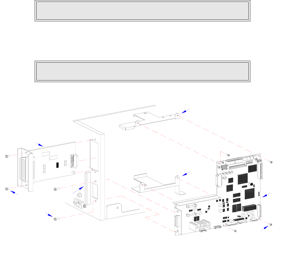
15 Secure interface board (3) to printer housing using two screws (2).
16 Reconnect all wiring harnesses to main circuit board (1).
17 Reconnect power supply cord, confirm correct potentiometer settings, and perform Factory
Reset.
18 Test cycle, and reattach housing covers.
Figure 7-6, Circuit Board Replacement
INTERFACE BOARD REPLACEMENT
1 Switch off the printer and disconnect the power supply cord.
2 Remove two screws (1, Figure 7-7) securing interface board (2) on the exterior back side of
printer.
3 Carefully withdraw interface board (2) from its connection with main circuit board (3).
4 Insert replacement interface board (2) through the housing slot to connect with main circuit
board (3).
5 Secure interface board (2) to printer housing using two screws (1).
6 Reconnect power supply cord and test cycle.
NOTE: Refer to Figure 10-5 of the Diagrams & Schematics section for wiring
harness connection locations if guidance is required.
NOTE: Figure 10-1 of the Diagrams & Schematics section provides guidance
on housing cover installation.
I
E
E
E
1
2
8
4
+
R
S
B
O
A
R
D
3
2
6
5
1
7
8
4


