G3 Air/Fuel Gauge
LC-1 Quick Start Guide
1. Wire the LC-1 per the unit’s instructions
2. Connect the gauge’s BROWN wire to a permanent/constant
12 volt source.
3. Connect the gauge’s BLACK ground wire at the LC-1’s
White ground point. This ground point should ideally be an
engine block ground.
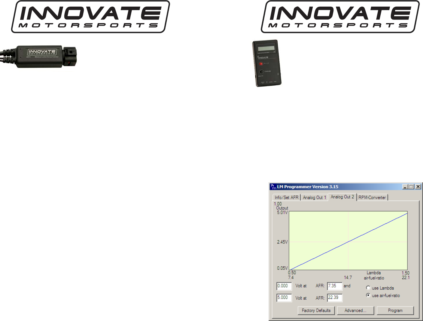
4. Connect the gauge’s GREEN wire to the LC-1’s Brown
analog output 2. The gauge is setup to work with the LC-1’s
analog output 2 factory default setting of 0v = 7.35 A/F and
5v = 22.39 A/F.
5. Connect the gauge’s WHITE and BLUE wires to a switched
12 volt source (ignition switched).
Optional Tip/Trick (requires connection of LC-1 to PC)
The LC-1 can be programmed to output specific voltages during
warm-up and error conditions. This can be done by connecting
the LC-1 to the computer and launching LM Programmer. The
warm-up and error condition options for the analog output are
under the Advanced… settings. For example, if you setup the
error condition at 5V your gauge will display full lean if any
problem arises. Please refer to chapter 6.5.1 in the LC-1 manual
for further information.
11-0116 g3 gauge.doc
G3 Air/Fuel Gauge
LM-1 Quick Start Guide
The LM-1’s analog output cable has three ends: Red wire
is analog output 1, White wire is analog output 2, and the
remaining wire is the ground. In these instructions we
will be using the white and ground wires.
1. Connect the gauge’s BROWN wire to a permanent/constant 12 volt
source.
2. Connect the gauge’s BLACK ground wire to the LM-1’s analog
output wire’s ground.
3. Connect the gauge’s GREEN wire to the white analog output wire.
4. Connect the gauge’s WHITE and BLUE wires to a switched
12 volt source (ignition switched).
5. Connect the LM-1 to the computer and launch LM Programmer.
Setup analog output 2 as 0v = 7.35 A/F and 5v = 22.39 A/F. Lastly
click on the “Program” button.


