


12-Volt 1-Mile Bi-Color
Pole Light with Task Light
5095
Installation Instructions
Attwood marine hardware, navigational lighting, bilge pumps, and
other marine accessories are specified more than any other brand by
America’s best-known boat manufacturers as original equipment.
Look to Attwood for quality replacement parts and marine accessories.
SAVE THESE INSTRUCTIONS
Form Number 69383 Rev. B 03-10
3
®
POLE LIGHT INSTALLATION
CAUTION:
All positive (+12V DC) wires must be fused to protect your circuits
and vessel. The Combination Light requires a 1-amp fuse. The Task
Light requires a 1-amp fuse and separate wire circuit. The aluminum
pole of the Universal Fit Light is not connected to an electrical
ground. (Figure 2)
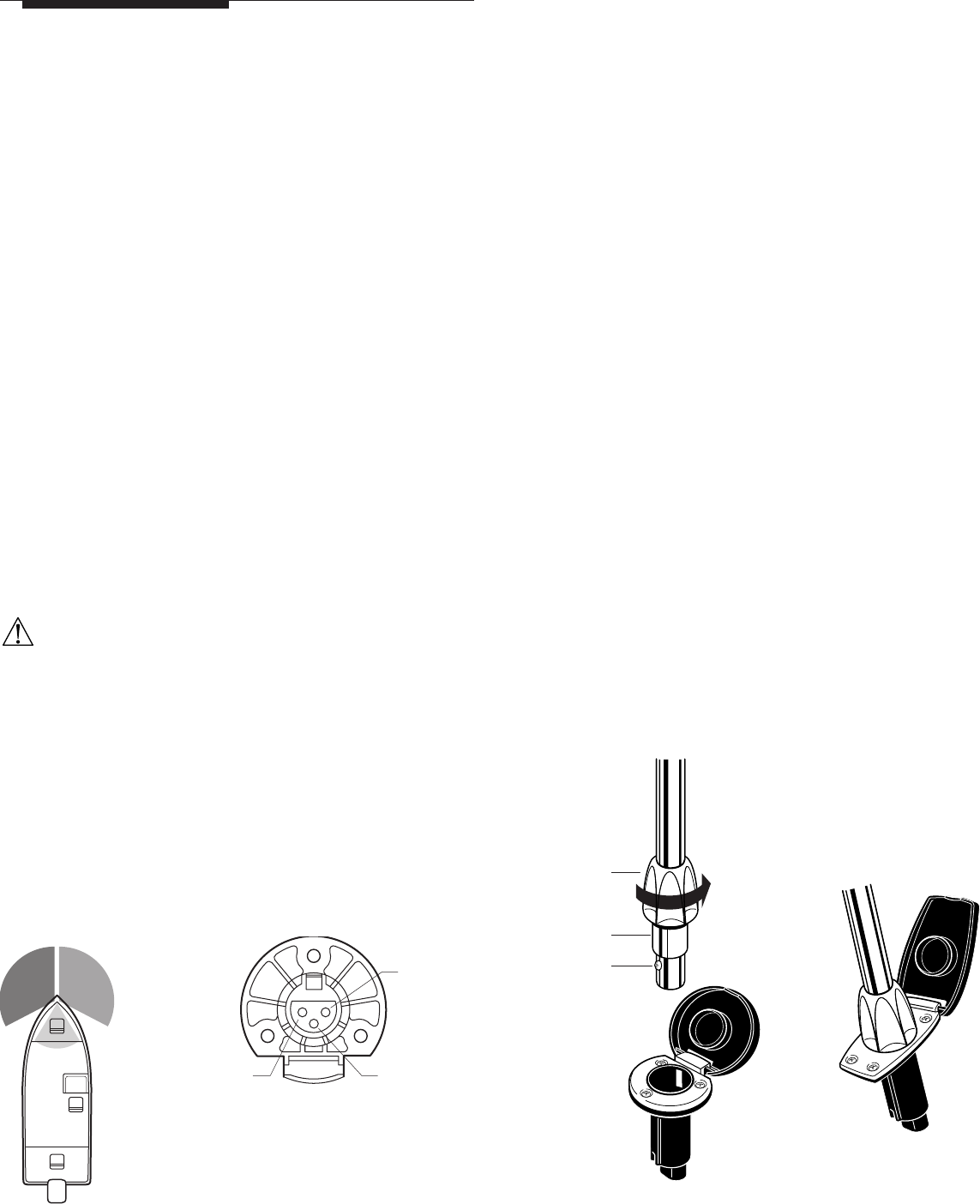
1.Insert pole into base, aligning screw with slot in base.
2.Press down firmly to engage electrical connectors.
3.Slide locking collar down to base, rotate until lower ring can be
inserted inside top of base.
4.Press down into base and rotate until locking collar tightens
between pole and base.
NOTE:
Periodically check pole to make sure it is secure.
5.To remove light, rotate locking collar in opposite direction until it
loosens, then pull up on pole. (Figure 3)
After installation, activate lights to verify proper operation. Navigation
light regulations require lights to be operated with a three-position
switch that provides for:
• Running lights (combination light and all-round light).
• Anchor lights (all-round light only).
• Off.
• Check the Task Light by pressing on switch at rear of light to turn
Task Light on. (Figure 4)
FEATURES
The Attwood 12-Volt, 1-Mile Navigation Combination Lights for boats
up
to 39.6 ft. (12 meters) incorporate a separately switched Task Light.
They feature impact resistant, UV-stable polycarbonate housings.
Certification: Bi-Color, 12-Volt, Sidelight with Tasklight.
Meets USCG CFR 183.810, ABYC A-16 requirements, and all applicable
standards as tested by Imanna Labs on 1/13/2003. 1 Nautical Mile
visibility. Uses 9235 #906 Lamp, 13V, 6 Candle Power.
REQUIRED FOR INSTALLATION
• Cordless drill with 1/8" (3mm), 3/8" (10mm) and 3/4" (19mm) bits.
• Screwdriver.
• Three #8 or #10 stainless pan head screws per light.
• Non-silicone sealant.
WARNING:
To prevent personal injury, always disconnect the power source
when installing or servicing this product. Always remove the boat
from the water before using 120V AC power tools.
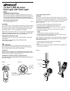
LOCATION
Lights must be mounted to an unobstructed smooth surface on the
gunwale, deck or superstructure. Locate Bi-Color Combination Light
in an area as far forward as possible. (Figure 1)
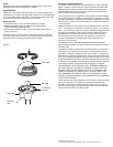
STANDARD 3-PIN BASE WIRING CONFIGURATION
For proper operation, the base that will accept the pole light must be
wired as in Figure 2.
Figure 1 Figure 2
Red Green
White
•
Locking Collar
•
Lower Ring
•
Screw
•
To +12-Volt
Navigation
Light Switch
•
To -12-Volt
Battery
•
To +12-Volt
Circuit with Fuse
(Powered Constantl
y
)
Figure 3