LED Anti-Glare All-Round Lights
5530 Series: Articulating Head LED Light
5540 Series: Articulating Head LED Light w/Folding Pole
Installation Instructions
SAVE THESE INSTRUCTIONS
Form Number 69422 Rev. A 07-06
3
®
Figure 1
Figure 2
© 2007 Attwood Corporation
1016 N. Monroe Street, Lowell, MI 49331-0260 www.attwoodmarine.com
EXTENDING AND FOLDING THE POLE (5540 Series)
The light is shipped with the pole folded and collars locked.
1. To unlock pole: Hold folded pole with lens upright. Pull the collar down (on lens half
of the pole). Pull the opposite locking collar up. This separates the collars. (Figure 2)
CAUTION: When unfolding pole, do not pinch fi ngers in hinge.
2. Press down fi rmly to engage electrical connectors. With Easy Lock Base, be sure
locking spring clicks over pole screw.
3. Slide locking collar down to base, rotate until you can insert lower ring inside top of base.
NOTE: Locking Collar stays above the Easy Lock Base
4. On bases other than the Easy Lock Series, press collar down into base and rotate
until it tightens between pole and base.
NOTE: Periodically check pole to make sure it is secure.
5. To remove:
• Pull locking spring back (on Easy Lock Base)
• On other bases, rotate locking collar in opposite direction until it loosens,
• Pull pole straight up.
TO CONVERT POLE FOR USE WITHOUT LOCKING COLLAR
1. For bases that do not accept locking collar, remove screw at bottom of pole. Slide
locking collar off end of pole.
2. Replace screw in the upper screw hole.
TO ADJUST ANTI-GLARE ARTICULATING HEAD
For best glare reduction, adjust the light while the boat is fl oating, or at the same attitude
as if it were fl oating.
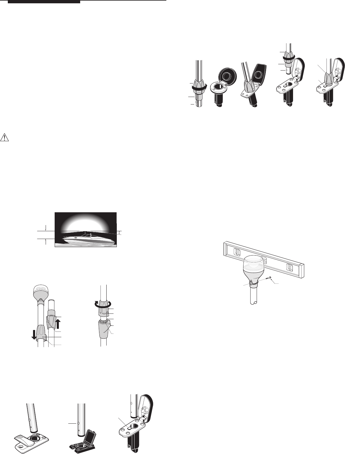
1. Remove the pivot screw. Pull the top pivot up and away from yoke. (Figure 5)
2. Place a small level against the lens and rotate to level position.
3. When it is level, push yoke and pivot back together. Replace and tighten screw.
(Do not over tighten.)
OPERATION
After installation, check lights to verify proper operation. Regulations require lights to
be operated with a three-position switch for:
1. Running lights (sidelights and all-round light);
2. Anchor lights (all-round light only);
3. Off.
BASE WIRING
IMPORTANT: LED-based lights MUST be wired for correct polarity. If your light does not
function after installation, the light base may require re-wiring. To re-wire if necessary:
1. Unscrew or remove the base so you can reach wiring.
2. Locate the connection between base wiring and the boat’s wiring harness.
3. Cut wires. Add waterproof splice to each wire end.
4. Reverse polarity by reversing original wire connection to the wire harness.
5. Temporarily plug light into the base to check operation.
6. Remove light and reinstall base.
NOTE: Do not use light pole as a fl agpole or handle.
MAINTENANCE
When not in use, store in Pole Light Storage Clips (Attwood #7571). Choose a storage
location where light will not be damaged or be in constant contact with water.
ATTWOOD LIMITED 10-YEAR WARRANTY
Because of the longevity of Attwood’s LED lighting technology, Attwood offers a limited
10-year warranty on this LED lighting product. See Product Catalog or attwoodmarine.com
for details.
Pivot Screw
Figure 5
7.5
One meter
or 39-3/8"
Locking Collar
Tab
Threads
CAUTION!
Pinch Point
Hinge Collar
Hinge
Hinge Collar
Groove
Tab
Pole Screw
•
Locking
Spring
•
Figure 3
2. Unfold pole so it is straight and threads are tight together. Slide hinge collar down
and turn onto threads. Hand-tighten only.
3. To fold and stow, reverse steps 1 and 2. Insert tab of hinge collar into groove of locking
collar. Press collars together.
INSTALLATION
Poles Without Locking Collar (5560 Series)
1. Align pole screw with the slot (or locking spring) in the existing base. Insert pole into
base (Figure 3).
#91020,
#91024,
or #91026
•
Locking
Collar
•
Lower
Ring
•
Screw
#91022
Locking
Spring
Locking
Collar
Locking
Collar
Lower
Ring
Screw
•
•
•
•
•
2. Press down fi rmly to engage electrical connectors. With Easy Lock Base, be sure locking
spring clicks over pole screw.
3. To remove:
• Pull locking spring back (on Easy Lock Base)
• Pull pole straight up.
Poles With Locking Collar (5530 Series)
1. Align pole screw with the slot (or locking spring) in the existing base. Insert pole into
base (Figure 4).
Figure 4
Lights meet USCG CFR 183.810, ABYC A-16 requirements, and all applicable standards
as tested by Imanna Laboratories, 5/3/2007. 2 nautical mile visibility.
CAUTION
Read all instructions carefully before installing and using this product. All positive (+12V DC)
lighting wires require a 1-amp fuse to protect circuits and vessel. The aluminum light
pole is not grounded.
MAKE SURE POWER SOURCE IS 12-VOLT DC ONLY. HIGHER VOLTAGE WILL DAMAGE
LIGHT AND CIRCUITRY.
WARNING
Disconnect power when installing or servicing this product. Remove boat from water
before using any 120V AC power tools.
LOCATION
5530 and 5540 Series All-Round Lights are designed for boats up to 39.4 feet (12m).
Position the all-round light so its LED light source is not less than one meter (39.4")
above sidelights. If replacing an existing pole light, replace with a pole at least as long
as the existing pole.
Mount the all-round light in a position so that: (Figure 1)
• Light output is fl at and parallel to water when boat is fl oating.
• Light shines 360°, unobstructed.
• Light does not shine on operator, or refl ect off any part of the boat in the operator’s
fi eld of vision.