PLANNING
GUIDE
Web: http://www.Dacor.com
Corporate Phone: 800-793-0093
Specifications are subject to change without notice.
See installation instructions for additional details.
CI.24
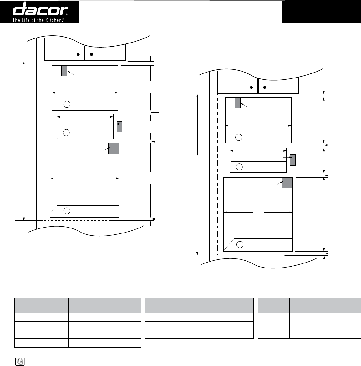
Microwave/Warming Drawer/
Classic Wall Oven
COMBINATION INSTALLATIONS
9 1/8"
(232mm)
27 1/2"
(699mm)
16 3/4"
(425mm)
1 1/2"
(38mm)
Min.
1 1/2"
(38mm)
Min.
“C”
“B”
“A”
120V
Microwave
Receptacle
240V
Wall Oven
Junction Box
1
1
1
7/8“ (22mm) Min.
1" (25mm)
Min.
58 1/4"
(1480mm)
Overall
Stacked
Height
120V Warming
Oven Receptacle
CUTOUT DIMENSIONS
DMT2420 ShOWN
9 1/8"
(232mm)
27 1/2"
(699mm)
19 1/8"
(486mm)
1 3/8"
(35mm)
Min.
1 5/8"
(41mm)
Min.
“C”
“B”
“A”
120V
Microwave
Receptacle
240V
Wall Oven
Junction Box
1
1
1
3/4“ (19mm) Min.
1" (25mm)
Min.
60 7/8"
(1546mm)
Overall
Stacked
Height
120V Warming
Oven Receptacle
CUTOUT DIMENSIONS
DCM24 ShOWN
Wall Oven
Models “C” Cutout Width
Single 27” 25 1/2” (648mm)
Single 30” 28 1/2” (724mm)
Single 36” 34 1/2” (876mm)
Microwave
Model No. “A” Cutout Width
DMT2420 w/Trim Kit 24 3/8” (619mm)
DCM24 w/ACTK27 25 1/4” (641mm)
DCM24 w/ACTK30 28 1/4” (718mm)
DCM24 w/ACTK36 25” (635mm)
Warming
Oven Models “B” Cutout Width
27” 25 1/2” (648mm)
30” 28 1/2” (724mm)
36” 34 3/8” (873mm)
1/1
Revised
09/04/08
All tolerances: +1/16”, -0, (+1.6mm, -0) unless otherwise stated
NOTE:
1. 3/4” (19mm) support platform (flush with cutout).
2. See individual appliance Planning Guide pages to
determine overlays.
3. Spacing between appliances and drawers/doors
shown is minimum required to allow for ventilation
and prevent scraping. Additional space may need
to be added for appearance.


