P.O. Box 100 • Hildebran, NC 28637 USA • 828-397-4200 • 828-397-4415 FAX
http://www.elkproducts.com • email: info@elkproducts.com
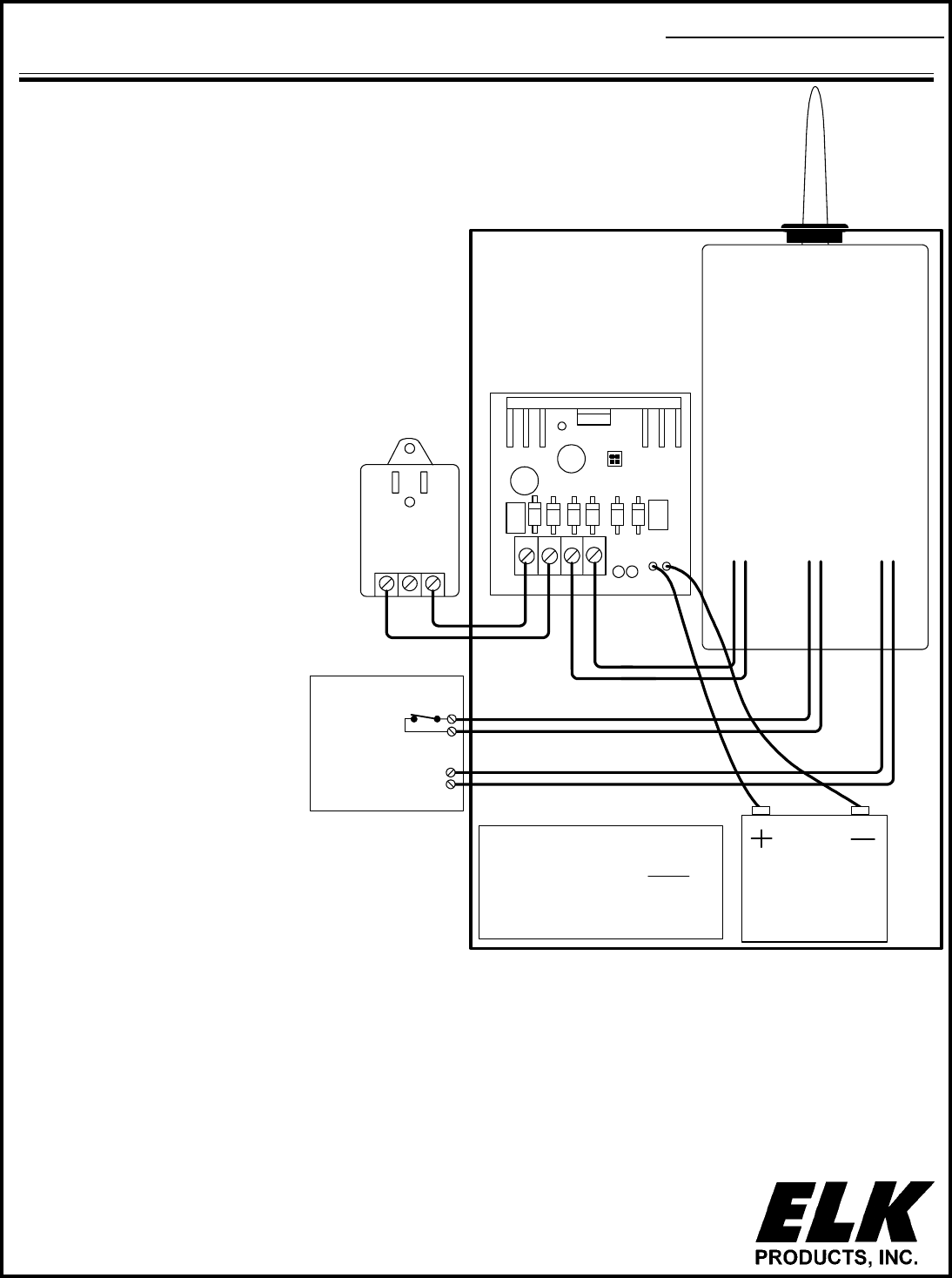
Black
Red
* Note:
Battery (ELK-1250) &
Transformer (ELK-TRG1640)
Included with ELK-982K
Sold Separately for ELK-982
-
Optional hookup
for Transmission
Shunt (if available)
Battery
12 Volt
* See Note
Transceiver
12 Volts D.C.
Power Input
Bell / Alarm
Input
Refer to the Cellular Transceiver
Instructions for Connections
Cellular
Alarm Transceiver
+
-
+
Bell / Alarm output
-
+
LED Status Indicators
(Grn)(Red)
AC DC Indication
ON / ON AC input is on / DC output is on. Normal.
OFF / ON AC input is off / DC output is from Battery only. Step
down Transformer is defective or unplugged, or the
AC outlet is off. Battery will eventually discharge.
ON / OFF AC input is on / DC output is off. The auto-reset
overload protector is likely open due to an overload
short circuit.
OFF /OFF AC input is off / DC output is off.
AC
TRANSFORMER
DC OUTPUT
AC DC
BATTERY
+
-
JP1
JP2
JP1 ON
JP2 OFF
ELK-624 12V POWER SUPPLY
LEDS
Line Fault output
Relay (contacts closed to
halt radio transmissions)
Control Panel
Do Not Move Jumpers
* See Note
Transformer
16.5 VAC
45 VA
- +
APPLICATION
The ELK-982(K) Cell-Pack is ideal for Cellular Alarm
Transceivers. It consists of a metal enclosure and 12 Volt
DC power supply/battery charger. It supplies 1 Amp
continuous current and 2.5 Amps peak for the brief high
current demands of the radio during transmission. The
design of the enclosure allows quick and easy field
mounting of the transceiver and antenna.
Cell-Pack
Power Supply, and Enclosure for
Cellular Alarm Transceiver
03/04
For Technical Support on the Numerex Technologies
Digicell Transceiver, call 888-987-5465.
FEATURES
• Supplies 12 Volts D.C. Power for Transceiver
• Current: 2.5A Peak, 1A Continuous
• Heavy Duty Metal Enclosure
INSTALLATION
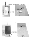
1. Mount transceiver in top right corner by sliding
antenna thru rubber grommet and securing the
bottom using hardware supplied. (see page 2)
2. Mount the ELK-P624 power supply board into the
enclosure as shown.
3. Wire as per the Cellular Transceiver instructions.
4. Connect Transformer and Battery after all wiring
is complete.
OPERATION
This hookup example shows the Transmission Shunt
Mode of operation. Control panel's that have phone
line fault monitoring will halt radio transmissions while
the phone line is good. Relay contacts on the control
panel will be closed to shunt any possible radio
transmissions.
If your control does not have line fault monitoring,
see ELK-981 which provides line fault monitoring
with power supply.
Features and Specifications subject to change without notice.
Includes Battery
& Transfomer
ELK-982K
ELK-982


