CCN 15252406
SELF EVACUATING OIL DRAIN
OPERATOR’S MANUAL
67384
RELEASED: 8-25-05
REVISED: 5- 25-10
(REV. 03)
INCLUDING: OPERATION, INSTALLATION & MAINTENANCE
READ THIS MANUAL CAREFULLY BEFORE INSTALLING,
OPERATING OR SERVICING THIS EQUIPMENT.
It is the responsibility of the employer to place this information in the hands of the operator. Keep for future reference.
OPERATING AND SAFETY PRECAUTIONS
WARNING
EXCESSIVE AIR PRESSURE. Can cause explosion resulting in
severe injury or death.
S Do not exceed the maximum inlet air pressure as stated on the model plate.
WARNING
EXPLOSIONHAZARD.Cancauseseriousinjuryorpropertydam-
age.
S Do not use near open flame or heat source.
S This product is notdesigned for working in explosive environments, including
those caused by fumes and dust, or near flammable materials.
WARNING
HAZARDOUS MATERIALS. Cancause personalinjury orproper-
ty damage.
S Do not use for volatile fuel and fluids.
S Obtain MaterialSafety DataSheets on all materialsfrom thesupplier forproper
handling instructions.
WARNING
HIGH PRESSURE AIR. Bypassing, modifying or removing the
safety /reliefvalve can causeserious injury ordeath. Do notbypass, modifyor
remove the safety / relief valve. Do not direct air stream at body.
CAUTION
Be certain all operators of this equipment have been trained for
safe working practices, understand it’s limitations and wear safety goggles /
equipment when required.
S Do not use for structural support.
S Disconnect air supply when not in use.
S Use only genuine IR replacement parts to assure longest service life.
GENERAL DESCRIPTION
Model67384is awasteoilcontainerwhichstoresupto 20gallons(75.7liters)inanASME
certified steel tank and rapidly discharges using air pressure. The unit is equipped witha
safetyrelief valvewhich prevents over-pressurization anda 5”x 16”(12.7cm x40.64 cm)
drain funnel with a filtering screen and a telescoping tube. The tank has (2) rigid casters
and (2) swivel casters for easy maneuvering. It also includes a sight gauge and a dis-
charge cam lock coupler.
OPERATION
1. To raisethefunnel:Grasptheupper portionofthe(5)tube,loosenthe(6)thumbscrew
and raise the funnel and tube to the desired height. Tighten the (6) thumb screw and
release grasp on tube.
2. To lower the funnel:
Grasp the upper portion of (5) tube, loosen the (6) thumb screw
and lower the funnel and tube to the desired position. Tighten (6) thumb screw and
release grasp on tube.
3. The reservoir includes a sight gauge. Do not overfill the reservoir.
4. To evacuateoil:
Lowerthe (1)funnel. Alwaysconnect thedischarge hosebeforecon-
nectingair supply. Connectthedischarge hoseto the(8)cam lockcoupler onthe(18)
tank.Be surethe (8)cam lockcoupler is fully engaged.Open the(9) oils hut offvalve.
Before connecting the air supply, besure thatthe inlet air linepressure isregu-
lated at no more than 70 p.s.i. (PMAX). Connect the air supply to the (10) air man-
ifold.Neverleavetheunitunattendedduringevacuation.Closethe(12)airshut-off
valve immediately when the tank is empty. The discharge hose will begin to shake
when the (18) tank is empty. Disconnect the airsupply to the (10) air manifold. Close
the(9)oilshutoffvalve.Slowlyopenthe(12)airshut-offvalvetodepressurizethesys-
tem. System must be depressurized before returning to service. Disconnect the dis-
charge hose from the (8) cam lock coupler on the (18) tank. Periodically remove and
clean the (2) funnel screen as necessary.
5. (17) safety relief valve may discharge during evacuation.
DATA
Weight 115 lbs (52.2 kgs)...............................
Recommended Air Operating Pressure 20 - 70 p.s.i.g. (1.38 - 4.83 bar)......
Capacity 20 gallons (75.7 liters).............................
Height (lowered) 52 in. (132.08 cm)...... ................
(fully extended) 73 in. (185.42 cm)...........
Tank Diameter 16 in. (40.64 cm).........................
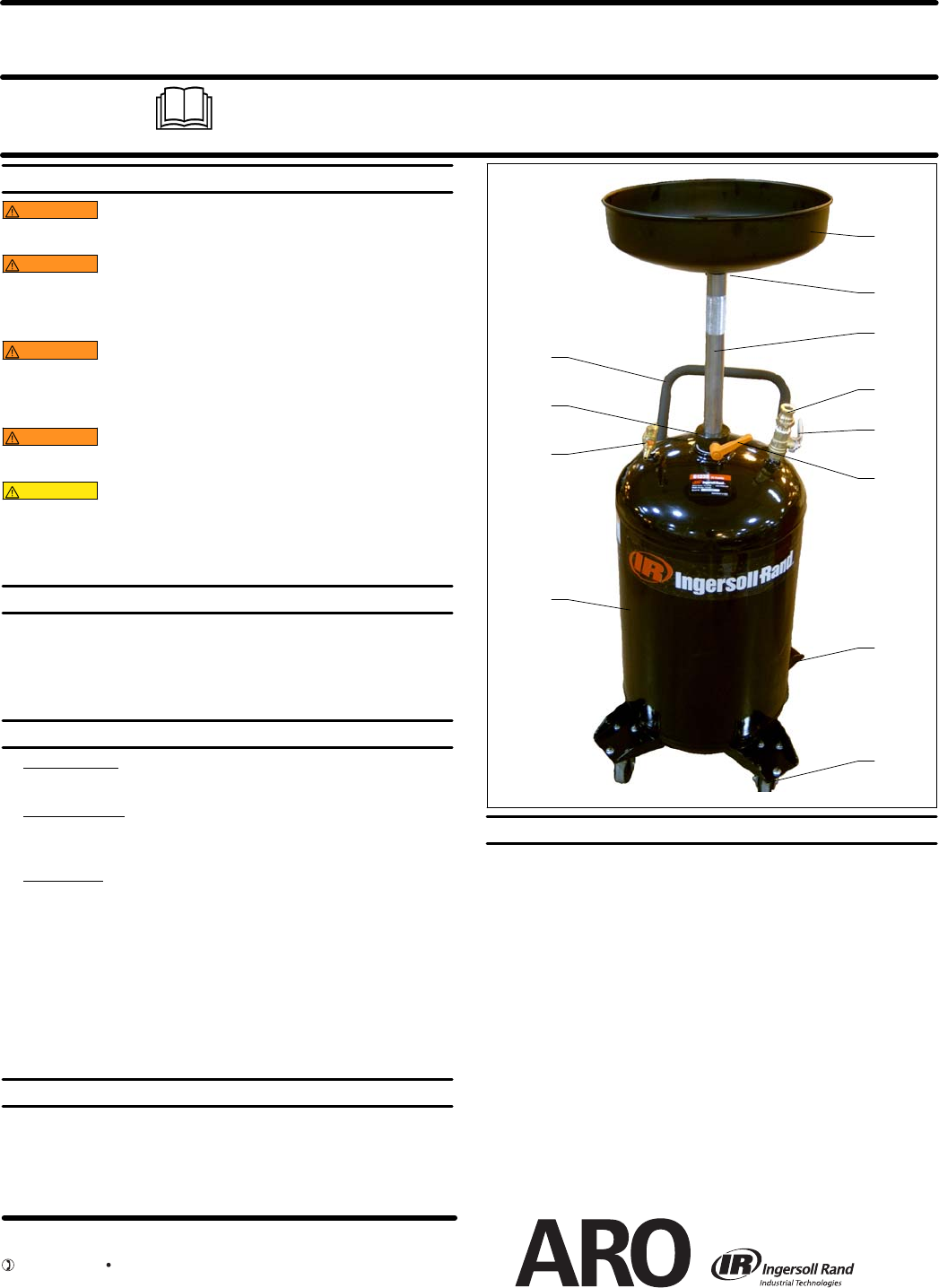
1
5
9
6
20
Figure 1
7
3
30
8
19
10
18
FLOAT VALVE SERVICE PROCEDURES
1. Depressurize system before and during servicing.
2. Wear appropriate safety equipment during servicing.
3. Remove (1) funnel from (5) tube.
4. Remove (6) thumbscrew from (7) c ollar.
5. Unbolt (30) handle and remove from the (18) tank.
6. Loosen the (7) collar and remove the (5) tube from the (18) tank.
7. To loosen the (7) collar, it may require the use of an industrial heat gun to soften the
pipe thread sealant on the (7) collar thread.
a. WARNING -- Do not use an open flame.
b. WARNING -- Be sure the tank vents are open during service.
c. WARNING -- Keep heat away from product labels.
8. Use a large spanner wrench or 12” pipe wrench to remove the (7) collar.
9. Secure tank when removing the collar.
10. Remove the (27) roll pin and the (25) ball from the (26) seat.
11. Remove the (26) seat by unscrewing the seat from the (5) tube.
12. Removedebrisandparticulatesfromthe(27)rollpin,(25)balland(26)seatusingmild
detergent and water.
a. WARNING -- Do not use solvent, as this may damage the ball.
13. Before reassembly, apply PTFE tape to the (26) seat threads.
14. Assemble inreverse order. Apply LoctitePST orequivalent pipethreadsealant tothe
(7) collar threads prior to assembly. Tighten securely.
15. Test all joints for air leakage prior to putting drain back into service.
INGERSOLL RAND COMPANY LTD
209 NORTH MAIN STREET – BRYAN, OHIO 43506
(800) 495-0276 FAX(800) 892-6276
© 2010
www.ingersollrandproducts.com


