


835961-UIM-D-0213
R-410A OUTDOOR SPLIT-SYSTEM
HEAT PUMP
MODELS: 13 SEER & 14.5 SEER -
THG(D,F)/GHGD/THJ(D,F)/YHJ(D,F)/YHJR/THJR SERIES
1.5 TO 5 TONS – 1 & 3 PHASE
INSTALLATION MANUAL
®
LIST OF SECTIONS
GENERAL . . . . . . . . . . . . . . . . . . . . . . . . . . . . . . . . . . . . . . . . . . . . . .1
SAFETY . . . . . . . . . . . . . . . . . . . . . . . . . . . . . . . . . . . . . . . . . . . . . . . .1
UNIT INSTALLATION . . . . . . . . . . . . . . . . . . . . . . . . . . . . . . . . . . . . .2
ORIFICE INSTALLATION . . . . . . . . . . . . . . . . . . . . . . . . . . . . . . . . . .5
TXV INSTALLATIONS . . . . . . . . . . . . . . . . . . . . . . . . . . . . . . . . . . . .5
EVACUATION . . . . . . . . . . . . . . . . . . . . . . . . . . . . . . . . . . . . . . . . . . .6
SYSTEM CHARGE . . . . . . . . . . . . . . . . . . . . . . . . . . . . . . . . . . . . . . .6
ELECTRICAL CONNECTIONS . . . . . . . . . . . . . . . . . . . . . . . . . . . . . 7
SYSTEM START-UP . . . . . . . . . . . . . . . . . . . . . . . . . . . . . . . . . . . . . 9
SYSTEM OPERATION . . . . . . . . . . . . . . . . . . . . . . . . . . . . . . . . . . . 10
INSTRUCTING THE OWNER . . . . . . . . . . . . . . . . . . . . . . . . . . . . . 12
WIRING DIAGRAM . . . . . . . . . . . . . . . . . . . . . . . . . . . . . . . . . . . . . 13
START UP SHEET . . . . . . . . . . . . . . . . . . . . . . . . . . . . . . . . . . . . . . 18
LIST OF FIGURES
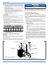
Typical Installation with Required Clearances . . . . . . . . . . . . . . . . . . .2
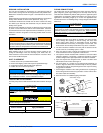
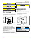
Tubing Hanger . . . . . . . . . . . . . . . . . . . . . . . . . . . . . . . . . . . . . . . . . . .3
Underground Installation . . . . . . . . . . . . . . . . . . . . . . . . . . . . . . . . . . .3
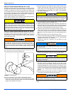
Heat Protection . . . . . . . . . . . . . . . . . . . . . . . . . . . . . . . . . . . . . . . . . .4
Orifice Installation . . . . . . . . . . . . . . . . . . . . . . . . . . . . . . . . . . . . . . . . .5
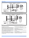
Outdoor Unit Control Box - Single Phase . . . . . . . . . . . . . . . . . . . . . . .7
Outdoor Unit Control Box - Three Phase . . . . . . . . . . . . . . . . . . . . . . .7
Typical Field Wiring (Air Handler / Electrical Heat) - (Three Phase) . .8
Typical Field Wiring (Air Handler / Electrical Heat) (Single-Phase) . . .8
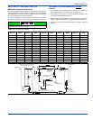
Heat Pump Flow Diagram . . . . . . . . . . . . . . . . . . . . . . . . . . . . . . . . . . 9
Time/Temp Control Module . . . . . . . . . . . . . . . . . . . . . . . . . . . . . . . 10
Demand Defrost Control Module . . . . . . . . . . . . . . . . . . . . . . . . . . . 10
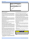
Defrost Operation Curves . . . . . . . . . . . . . . . . . . . . . . . . . . . . . . . . . 12
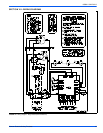
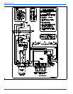
Wiring Diagram - Single Phase (Demand Defrost) . . . . . . . . . . . . . . 13
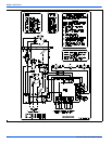
Wiring Diagram - Single Phase (Time-Temp) . . . . . . . . . . . . . . . . . . 14
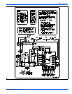
Wiring Diagram - Three Phase (Demand Defrost) . . . . . . . . . . . . . . 15
Wiring Diagram - Three Phase (Time-Temp) . . . . . . . . . . . . . . . . . . 16
LIST OF TABLES
R-410A Saturation Properties . . . . . . . . . . . . . . . . . . . . . . . . . . . . . . .9
TEST Input Functionality . . . . . . . . . . . . . . . . . . . . . . . . . . . . . . . . . .10
X/L Output Categories . . . . . . . . . . . . . . . . . . . . . . . . . . . . . . . . . . . 10
Defrost Initiate Curves . . . . . . . . . . . . . . . . . . . . . . . . . . . . . . . . . . . 11
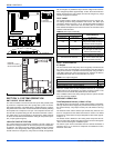
SECTION I: GENERAL
The outdoor units are designed to be connected to a matching indoor
coil with sweat connect lines. Sweat connect units are factory charged
with refrigerant for a matching indoor coil plus 15 feet of field supplied
lines.
Matching indoor coils are available with a thermal expansion valve or
an orifice liquid feed sized for the most common usage. The orifice size
and/or refrigerant charge may need to be changed for some indoor-out-
door unit combinations, elevation differences, or total line lengths. Refer
to Application Data covering “General Piping Recommendations and
Refrigerant Line Length” (Part Number 247077).
SECTION II: SAFETY
This is a safety alert symbol. When you see this symbol on
labels or in manuals, be alert to the potential for personal
injury.
Understand and pay particular attention to the signal words DANGER,
WARNING, or CAUTION.
DANGER indicates an imminently hazardous situation, which, if not
avoided, will result in death or serious injury
.
WARNING indicates a potentially hazardous situation, which, if not
avoided, could result in death or serious injury
.
CAUTION indicates a potentially hazardous situation, which, if not
avoided may result in minor or moderate injury
. It is also used to
alert against unsafe practices and hazards involving only property dam-
age.
INSPECTION
As soon as a unit is received, it should be inspected for possible dam-
age during transit. If damage is evident, the extent of the damage
should be noted on the carrier’s delivery receipt. A separate request for
inspection by the carrier’s agent should be made in writing. See Local
Distributor for more information.
Improper installation may create a condition where the operation of
the product could cause personal injury or property damage.
Improper installation, adjustment, alteration, service, or maintenance
can cause injury or property damage. Refer to this manual for assis-
tance or for additional information, consult a qualified contractor,
installer, or service agency.
This product must be installed in strict compliance with the enclosed
installation instructions and any applicable local, state, and national
codes including, but not limited to building, electrical, and mechanical
codes.