


Page 2
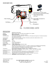
WIRING DIAGRAMS:
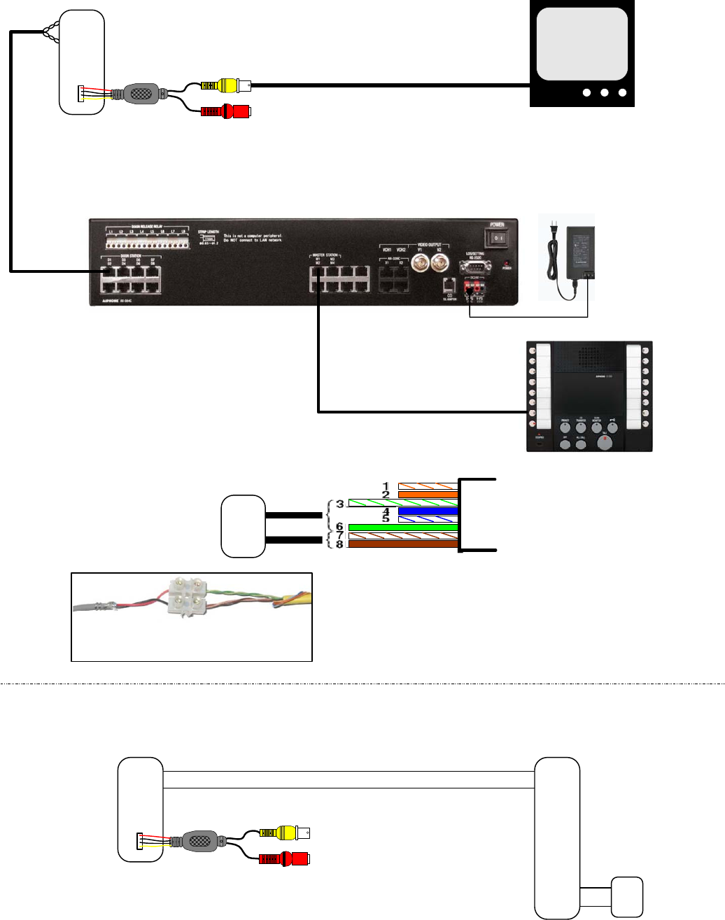
Homerun each sub to
AX-084C, AX-248C, or
AX-320C CEU.
Red
Blk
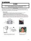
IE-SSV
TIA/EIA 568B Standard:
Connect 3/6 pair (green) to “Red”
Connect 7/8 pair (brown) to “Black”
CAT5e
Illustration of converting from
2-conductor to CAT-5e cable.
Use your preferred method for splicing cables to
interface a standard 2-conductor cable run from
the door station to the CAT-5 cable and RJ45
jack, required for connection to the CEU.
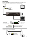
AX System with AX-8M master and pinhole camera being viewed on standard monitor:
Splice 2 wires of IE-SSV to Cat5E wire as shown: See wiring diagram below.
Red
Blk
IE-SSV
12V DC power input for camera
(Red - Must use supplied transformer)
Video output to monitor
or CCTV system (Yellow)
Standard CCTV
Monitor
AX-8M
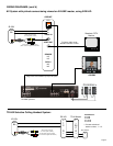
IE Series Chime Tone Door Answering System:
Red
Blk
IE-SSV
12V DC power input for camera
(Red - Must use supplied transformer)
Video output to monitor
or CCTV system (Yellow)
D1
E1
L
L
+
-
IE-1AD
IE-1GD
IE-2AD
+
-
Power
Supply
AX-084C pictured