


3. PRE-INSTALLATION CHECKLIST
IMPORTANT STEPS AND DECISIONS
REQUIRED BEFORE INSTALLATION
4. REQUIRED COMPONENTS AND
ACCESSORIES CHECKLIST
j
THIS PRODUCT MUST BE INSTALLED AND
MAINTAINED BY A LICENSED PROFESSIONAL. IN
ADDITION TO THE INSTRUCTIONS IN THIS MANUAL,
FOLLOW ALL APPLICABLE LOCAL AND STATE
CODES OR IN THE ABSENCE OF SUCH CODES, THE
CURRENT EDITIONS OF THE NATIONAL PLUMBING
CODE AND THE NATIONAL ELECTRIC CODE.
j
DRIP PAN AND DRAIN: To avoid leaking and/or flooding
damage, install with a drip pan connected to an adequate
working drain kept clear at all times.
j
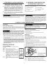
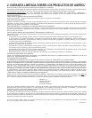
1. PRESSURE SWITCH
j
2. RELIEF VALVE
j
3. 1 UNION
j
4. 1 SHUT OFF VALVE
j
5. VALVE DRAIN
j
6. PRESSURE GAUGE
j
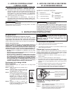
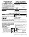
7. TANK-TEE
VERTICAL STAND MODELS
MAXIMUM WORKING PRESSURES
Every well tank is air tested to 100 psig,
the maximum working pressure for the well tank line.
RELIEF VALVE RECOMMENDED
It is recommended that a relief valve
be installed which is set to open at excessive pressures (75
psig or more). This will protect your well tank and other system
components should the pressure switch malfunction and fail to
shut the pump off. The relief valve should be installed at the
connection of your well tank to the system piping and have a
discharge equal to the pump’s capacity at 75 psig.
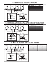
5. INSTALLATION INSTRUCTIONS
Location
Proper well tank Location
The well tank should be installed as close as possible to the
pressure switch. This will reduce the adverse effects of added
friction loss and pressure switch bouncing, and the difference in
elevation between well tank and switch.
DANGER! EXPLOSION HAZARD. WHEN THE WELL
TANK HAS BEEN IN SERVICE AND A CHANGE TO
A HIGHER PRE-CHARGE PRESSURE IS NECESSARY DUE TO A REQUIRED
CHANGE IN THE PRESSURE SWITCH SETTING, FAILURE TO FOLLOW
INSTRUCTIONS BELOW CAN CAUSE A RUPTURE OR EXPLOSION, POSSIBLY
CAUSING SERIOUS OR FATAL INJURY, AND/OR PROPERTY DAMAGE.
• DO NOT ADJUST OR ADD PRESSURE IF THERE HAS BEEN A LOSS OF
AIR.
• DO NOT ADJUST THE PRE-CHARGE PRESSURE IF THERE IS VISIBLE
EXTERIOR CORROSION.
• DO NOT ADJUST THE PRE-CHARGE PRESSURE IF THERE HAS BEEN A
REDUCTION OF THE PUMP CYCLE TIME OR THE PRE-CHARGE PRESSURE
COMPARED TO ITS INITIAL SETTING. THIS IS BECAUSE REDUCTION IN PUMP
CYCLE TIME CAN RESULT FROM LOSS OF TANK AIR PRESSURE WHICH
IN TURN CAN MEAN THERE MAY BE INTERNAL CORROSION AND ANY
RE-PRESSURIZATION OR ADDITIONAL PRESSURE COULD RESULT IN
RUPTURE OR EXPLOSION.
Adjusting Precharge
Prior to Installation
All well tanks are shipped with a standard precharge
of 38 psig.
Step 1. Remove protective air valve cap
Step 2. Check precharge pressure should be + or -
10% of the factory setting)
Step 3. Release or add air as necessary to make
the precharge pressure 2 psig below
the pressure switch pump cut-in setting.
(Example, if you have a well tank with
a precharge of 38 psig, and you have
a pressure switch setting of 30/50 psig,
adjust precharge of your well tank from 38
psig to 28 psig.)
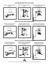
Step 4. Replace protective air valve cap. Peel off
backing of label and apply over air valve
cap.
Explosion Hazard. Failure to follow
these instructions can cause a
rupture or explosion possibly causing serious or fatal
injury, flooding, and / or property damage.
System Connection
1. Locate your well tank in the final desired location.
2. Level as necessary.
3. To eliminate friction loss, do not reduce the pipe size from the
pump to the well tank.
Start Up
Fine Tuning Procedures
Many times the actual pressure switch will vary from the standard
pressure range indicated. These variations could cause a momentary
lag of water delivery, as the pressure switch is not “tuned to the well tank
precharge pressure”.
1. Fill the system and well tank until pump cuts off.
2. Open one or more fixtures to drain the well tank.
3. If there is a momentary pause in the water flow from the time the well
tank is emptied and the pump starts, adjust pump cut-in setting clock-
wise slightly (see figure 2).
4. Close fixtures and refill well tank to pump cut off. Check time to fill.
5. Open fixtures and see if pause in water is eliminated. If not, con-
tinue adjusting pressure switch.
FIGURE 2
Pressure Adjustment Clockwise
To Increase Cut-Out Pressure
Counter Clockwise To
Decrease Cut-Out Pressure
Adjusting Precharge After Installation
Step 1. Drain tank of all water. Check precharge pressure in the
well tank.
Step 2. Release or add air as necessary to make the precharge
pressure 2 psig below the pressure switch pump cut-in setting.
AIR V A L VE
LABEL
AIR
V A L VE
CAP
AIR V A LVE LABEL
IN POSITION
OVER CAP
FIGURE 1
-4-