


EXPLOSION HAZARD. Failure to follow
instructions in the accompanying product manual
can cause rupture or explosion, possibly causing serious or fatal injury,
leaking or flooding and/or property damage.
FAILURE TO PROPERLY SEAL VALVE CAP
WILL RESULT IN LOSS OF PRECHARGE
CAUSING PRODUCT TO FAIL.
Location of EXTROL
®
Expansion Tanks
DO NOT LOCATE THIS PRODUCT WHERE
LEAKING OR FLOODING COULD CAUSE
DAMAGE TO THE SURROUNDING PROPERTY.
This Product, like most Products under pressure,
may over time corrode, weaken and burst or explode,
causing serious or fatal injury, leaking or flooding and/or property damage.
To minimize risk, a licensed professional must install and periodically
inspect and service the Product. A drip pan connected to an adequate drain
must be installed if leaking or flooding could cause property damage. Do
not locate in an area where leaking could cause property damage to the
area adjacent to the appliance or to lower floors of the structure.
The AMTROL expansion tank may be placed in any convenient position
within the mechanical room (or building). If multiple tanks are installed,
they should all be on the same level.
Point of Connection
Unlike a conventional tank, the EXTROL sealed air cushion does not
require replenishment so DO NOT connect to an air separator or other
air collection device.
As with any expansion tank, it is recommended that the EXTROL be
connected to the suction side of the pump. This will prevent the pump
head from becoming subtractive which may result in entry of air and
vapor formation at high points in the system.
By connecting the EXTROL on the boiler return, displacement of coolest
system water into tank is ensured reducing energy waste.
Low pressure drop components such as air separators and boilers may
be placed between point of connection and pump suction if desired.
System design will dictate the feasibility of this.
Natural convection losses and the entry of air into tanks are eliminated
by
connection to the side or underside of main pipe. The piping should be pitched
up and away from the EXTROL to eliminate any potential air traps.
Installation
THIS PRODUCT MUST BE INSTALLED BY A
QUALIFIED PROFESSIONAL.
1. Note location of system connection, air charge valve and drain
connection on tank.
2. Remove the plug or pipe cap from the system connection.
3. Remove the 1 1/2” NPT plug covering the air charge valve.
4. Before making any connection to the tank, check the tank and air
charge (use an accurate pressure gauge). The air pressure must be
equal to the minimum system pressure at the tank location.
IMPORTANT: If increasing pre-charge pressure above
55 psig the following steps must be followed:
a. Tank must be connected to the system with the isolation valve
open.
b. System must be pressurized to 13-14 psig, slightly above
factory setting.
c. Isolation valve needs to be shut.
d. Pre-charge pressure of tank can now be increased to match
system fill pressure.
e. Open isolation valve and start up system.
Failure to follow these steps could result in damage to the
bladder and void all warranties.
5. After making sure the air charge is correct, replace the valve cap and
the 1 1/2” plug over the air valve.
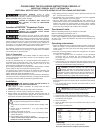
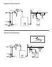
6. The EXTROL may now be piped to the system (use the suggested
EXTROL piping diagrams on the next page).
7. Using the table below, select appropriate pipe size. Connection to
each EXTROL must have a lock shield gate valve and union to allow
isolation and removal if required. Make up and fill valves, whether
manual or automatic, should be tied into the connecting line. This will
ensure that pump operation will not affect valve operation.
Operational Limits
Maximum Operating Pressure: As stamped on nameplate
Maximum Operating Temperature: 240 °F
Minimum Operating Temperature: 35°F (non-glycol application)
If unit is being installed in a glycol system where minimum temperatures
fall below 35°F, contact the AMTROL technical service department at
(401) 535-1216.
Operating Instructions
1. Check the expansion tank pre-charge before the system is filled with
water. The charge is 12 psig unless noted otherwise on the tank label.
Check to make sure this is the correct pre-charge pressure specified
for the system.
2. If the tank pre-charge pressure needs to be changed on a dry system
follow the following procedure:
a. Check the expansion tank air pressures at the pre-charge
connection with an accurate tire type pressure gauge. The
pre-charge connection is the same kind of connection found on
automobile tires.
b. If the pressure is low, charge the tank with nitrogen gas or with
oil free compressed air. Check the pressure frequently during this
process as you would when filling a tire with air.
DANGER: Excessive pressure can cause tank to
explode. Exercise care when filling a tank with air so
the pressure does not exceed that required or does
not exceed the working pressure of the tank as stamped on the
nameplate. Failure to follow these instructions will result in
serious personal injury or death and property damage.
3. If, after the system has been filled with water and operating, it is found
that the expansion tank pre-charge must be changed use the following
procedure:
a. Turn off the heat source and allow the system water to cool to
ambient temperature.
IMPORTANT: Expansion tank cannot be properly air
charged other than at ambient temperature.
b. Close the lock-shield valve in the tank-to-system piping.
c. Open the drain valve to empty the water from the tank.
d. Check the tank air pressure at the pre-charge connection with an
accurate tire type air gauge.
e. Refer to 2b above.
f. Close the drain valve, open the lock-shield valve and turn on the
heat source.
g. Relock the lock-shield valve.
PLEASE READ THE FOLLOWING INSTRUCTIONS CAREFULLY
IMPORTANT GENERAL SAFETY INFORMATION -
ADDITIONAL SPECIFIC SAFETY ALERTS APPEAR IN THE FOLLOWING INSTRUCTIONS.
Firing Rate Length of Pipe Connecting
of Boiler Tank to System:
MBTU/H Below 11' 11' – 30' 31' – 100'
2,000
1
/2"
3
/4" 1"
4,000
3
/4" 1" 1
1
/4"
8,000 1" 1
1
/4" 1
1
/2"
12,000 1
1
/4" 1
1
/2" 2"
16,000 1
1
/4" 2" 2
1
/2"
20,000 1
1
/2" 2" 2
1
/2"
Warranty
L Series Models: One (1) Year Limited Warranty
Visit www.amtrol.com for complete warranty details.