


Sizing Chart
Amtrol
Pressuriser
®
Minimum
Flow Rate
From City
Supply
Minimum
Flow Pressure
From City
Supply
Minimum
Incoming
Pipe Size
Water
Meter
RP-10HP 10 gpm 10 psig
3
/4"
3
/4"
RP-15HP 15 gpm 10 psig 1" 1"
RP-25HP 25 gpm 10 psig 1
1
/4" 1
1
/4"
Metal piping must be used for all inlet and outlet lines to the unit.
Do not oversize pump. Inadequate water supply will result in
poor performance and pump damages.
Pre-Installation
• DONOTUSEFORPRE-HEATEDWATERSUPPLIES;
• DO NOT USE FOR ANYTHING EXCEPT COLD WATER
(AMBIENTTEMPERATURENOTTOEXCEED100°F);
• DO NOTUSE INSYSTEMS WHERELOW PRESSUREIS
DUE TO LEAKS OR WHERE LEAKS IN THE PLUMBING
SYSTEMMAYEXIST;
• DONOTUSEINSYSTEMSWHERETHEWATERSUPPLY
CANDROPBELOW10PSIG;
• DO NOTUSE IN SERIESWITH ANOTHERPUMP (SUCH
ASINPRIVATEWELLWATERSYSTEMS);
• DO NOT RE-PRESSURIZED TANK AFTER INITIAL
INSTALLATION;
• DO NOT PIPE EXCEPT WITH METAL PIPING AT INLET
AND OUTLETS.
The system must be placed indoors only on a solid level
surface with a drip pan piped to a drain with adequate capacity
for large volumes of water in the event the system ruptures or
fails. Consider the risks posed by tanks under pressure and the
potential for leaking and/or flooding damage in selecting the
location. The unit must not be placed in an environment that would
expose the water in the tank to temperatures below freezing or in
excess of 100° F.
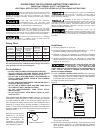
Be sure to leave a minimal
clearance of 12” around
the unit for access should
field adjustments be
necessary in the future
and to permit maintenance
and inspection (Figure 1).
Installation
1. Remove protective air valve cap.
2. Check pre-charge pressure (pressure should be + or – 10% of
the factory setting). Factory pre-charge is 38 psig.
3. Release or add air as necessary to make the pre-charge
pressure 2 psig below the pressure switch pump cut-in setting.
4. Replace protective air valve cap. (Remove air valve label,
replace protective air valve cap, peel off backing of label and
apply on air valve cap.)
MINIMUM SUPPLY LINE AND METER SIZE FOR
THE RP-10HP IS
3
/4", THE RP-15HP IS 1" AND
THE RP-25HP IS 1
1
/4". THIS APPLIES TO ALL LINES INCLUDING
THOSE USED WITH THE WATER METER OR FITTINGS BEFORE THE
PUMP. CONTACT FACTORY IF MINIMUM FITTING/LINE SIZE IS
BELOW THE ABOVE NUMBERS.
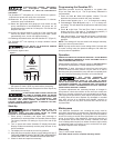
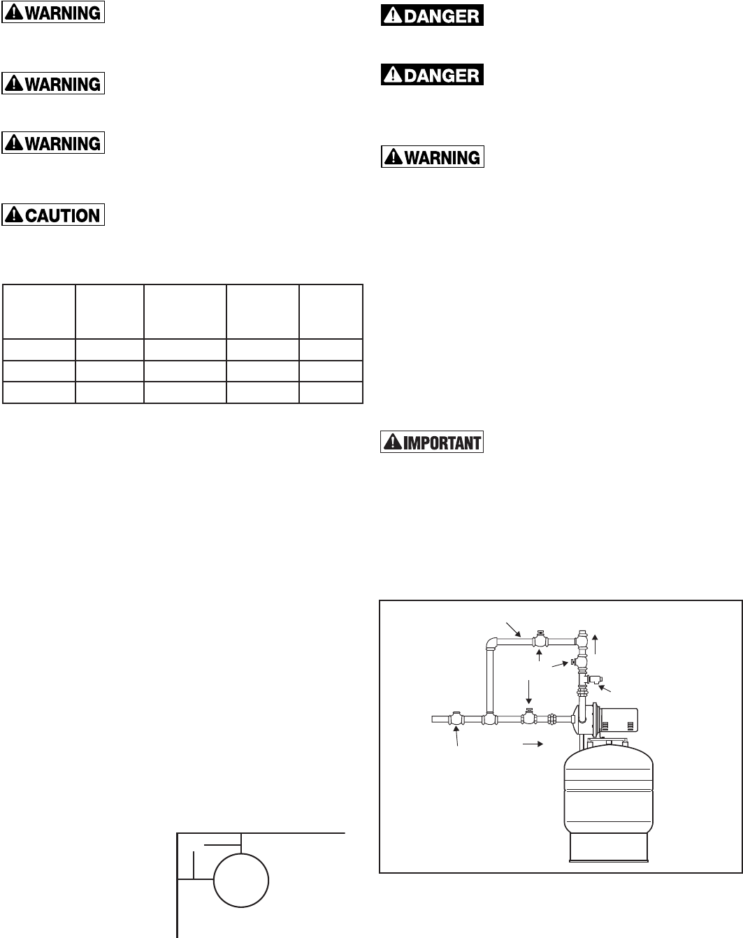
5. Install a SPRING LOADED CHECK VALVE in the city supply
line on the suction side of the pump along with a shut-off valve.
Failure to do so will result in premature failure of the AMTROL
Pressuriser due to excessive pump cycling.
6. Install a by-pass loop (Figure 2).
7. Pipe the city supply after the shut-off valve to the suction side
of the pump, as shown.
8. Connect the house supply line using a 100 psig maximum relief
valve as shown (Figure 2). It is important that the pressure
relief valve be installed on the pump discharge prior to any
shut off valves.
PLEASE READ THE FOLLOWING INSTRUCTIONS CAREFULLY
IMPORTANT GENERAL SAFETY INFORMATION -
ADDITIONAL SPECIFIC SAFETY ALERTS APPEAR IN THE FOLLOWING INSTRUCTIONS.
If the control is set too high or the pump is running
when the water supply is shut off and there is no
demand on the system, the pump will run continuously, can overheat
and become damaged, potentially resulting in product failure, leaking
and/or rupture.
All wire and fuse sizings are preliminary
recommendations only. For your safety, local
codes, and in their absence, national codes must be followed to minimize
the risk of electric shock, property damage or personal injury.
The pump motor is designed for use with single
phase, 60Hz ac. Use with any other type of power
will cause damage to the motor. The pump models RP-10HP, RP-15HP
and RP25-HP are pre-wired for 115 vac; however, they can be rewired to
be used with 230 vac. Consult motor nameplate for the wiring diagram.
The power for your pump must be on a dedicated
circuit. In addition, a shut off switch should be
visible and near the pump. Use a 20 amp circuit.
Before attempting any service and disassembly,
shut off power to the pump. Ensure power is
disconnected prior to removing motor. Ensure power is disconnected
before cleaning is attempted.
Grounding of the pump is essential for your
protection and the protection of the motor. All wiring
should be completed by a licensed electrician, and in accordance with
local codes or in their absence, the National Electrical Code. Before
starting the wiring installation, disconnect all power to the circuit to be
used for the AMTROL Pressuriser
®
.
The AMTROL Pressuriser
®
should only be
connected to a municipal, cold water supply, and in
systems with a minimum pressure of 10 psig at all times, measured under
flow at the tap closest to the location of the AMTROL Pressuriser
®
installation.
12"
Amtrol Pressuriser
®
Figure 1
SPRING
CHECK VALVE
FLOW
FLOW
BYPASS
LOOP
PRESSURE
RELIEF
VALVE
CITY
WATER
SUPPLY
TO SYSTEM
SHUT-OFF
VALVES
RP-10HP
RP-15HP
RP-25HP
Figure 2