Owner’s Manual
TSD-DCPDV
DC Power Distribution
AtlasSound.com – 4 –
Specifications are subject to change without notice.
1601 Jack McKay Blvd. • Ennis, Texas 75119 U.S.A.
Telephone: 800.876.3333 • Fax: 800.765.3435
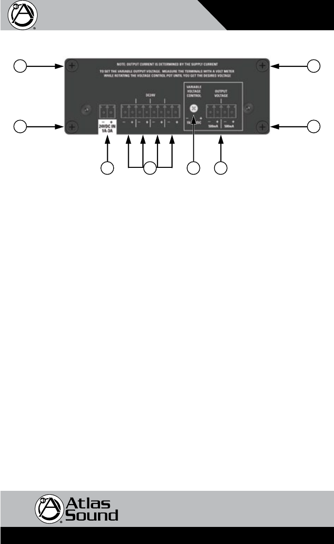
Rear Panel Description
TSDInput/Outputconnectionsareremovableforeasysystemwiring.Theconnectorhasa3.5mm
pitch between pins.
1. DC Power Input - Each TSD that requires DC power comes with a 2 position connector for
an external 24VDC power supply (sold separately). Because of the TSD’s low power consumption,
asingleexternalpowersupplymaypowermorethanoneTSD.Pleaserefertothespecications
on current requirements in milliamps to match with the appropriate power supply. Note: It is
acceptable to exceed the current requirements of the TSDs but NOT safe to use a power supply
that is below the current requirement of the device.
2. Isolated DC Outputs - Connect all system TSD products to these outputs, ensuring the total current
draw of all the connected devices does not exceed the supply current of the TSD power supply
being used. Observe the polarity of the output connectors and the polarity of the TSD devices
beingconnectedaswell.Eachoutputislteredandisolated.
3. Variable DC Voltage Control-Rotateclockwisetoincreasethevoltageatthe2variableoutput
voltageconnectors.Rotatecounterclockwisetodecrease.Ametershouldbeusedtomeasure
the DC voltage at the output terminals. Adjustment range is 5-24VDC when a 24VDC power supply
is connected to the 24VDC Input.
4. Variable Output Voltage Connectors - Connect devices to these two outputs that require a voltage
otherthanxed24VDC.Observethepolarityattheconnectors.Maximumcurrentoutputis500mA
at each port.
5. Cable Management Retainer Points - Each TSD includes two cable retainer straps for securing
theincludedcablemanagementretainers.Removeoneoftherearpanelscrews,alignthe
panelholewitharetainerandrmlytightenthescrews.
1 42
55
5 5
3


